Chapter 7: Direct Current Motors
Chapter 7: Direct Current Motors. Theory of Operation. Force is exerted on a current carrying conductor in a magnetic field. Simple DC Motor Commutation: Periodic reversal of current Torque is greatest when Parallel (most flux). DC Motor Theory

Chapter 7: Direct Current Motors
E N D
Presentation Transcript
Theory of Operation • Force is exerted on a current carrying conductor in a magnetic field.
Simple DC Motor • Commutation: Periodic reversal of current • Torque is greatest when Parallel (most flux)
DC Motor Theory http://hyperphysics.phy-astr.gsu.edu/HBASE/magnetic/motdc.html • DC Motor Java Applet http://www.magnet.fsu.edu/education/tutorials/java/dcmotor/index.html • Flash of various motors http://www.st.com/stonline/products/support/motor/tutorial/motor.swf
DC Motor theory http://www.youtube.com/watch?v=Xi7o8cMPI0E http://www.youtube.com/watch?v=FjNnRyLexNM
DC Motor cutaway • Bearing • Case/end bell • Brush holder • Rotor Windings (Armature) • Brushes • Commutator • Stator windings (Field) (permanent magnetsin this motor) • Armature Bars
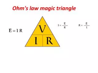
Toque is based on Armature Current and Magnetic Flux of the fieldT = kTIA • Generator Action: Moving a conductor though a field produces a voltage (EMF) – based on flux and speed:EMF = KESIn a motor this EMF is opposite applied voltage.
Induced voltage counters applied voltage, and is called counter EMF or CEMFVa = Vin – CEMF • Ia = (Vin – CEMF)/Ra • Speed therefore is:S = CEMF/KE
CEMF is prop to speed x fluxCEMF S • Armature Current is prop to applied voltage - counter EMF IA Vin – CEMF • Torque is prop to armature current x FluxT IA • Speed is proportional to TorqueS
Speed Regulation: ability of a motor to maintain rated speed under load. Based on no-load and full-load speed.%speed regulation = (SNL-SFL)/SFL X 100
Series-Wound Motor • Initial current is very high until motor comes up to speed. • Provides large starting torque – Car starters. • Under no-load can run-away (over speed)
Stall Torque – Maximum torque a motor can supply without stalling • No-Load Speed – Speed of motor with no load. Any motor that is doing something useful must be running at less than no-load speed. • Reversing applied voltage does NOT change motors direction. Changing only armature connections would.
Shunt-Wound • Lower stall and no-load speeds. • Much less speed change from NL to FL (15%) • Speed control via line voltage. • Reversing only shunt or armature will reverse motor.
Compound Motor • Combination of series and shunt. • Good starting torque and good speed control.
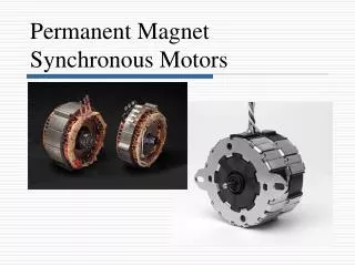
Permanent Magnet Motors • High flux permanent magnets provide flux. • Very good linear control • Low power use
DC Motor Control • Adjusting voltage or using PWM
PWM Speed Control • By cycling the voltage fully on and off within a small time, the speed can be controlled. • The higher the on-time, or duty cycle, the more power that is received.
Problems: • Higher frequencies lead to higher power dissipation by driver (more time switching). • Due to inductance, current will lag and may not be linear with shorted/faster duty cycles.
Braking • Braking: Since a motor generates voltage, by applying a load when power is removed, the generated power is consumed by a load resistor absorbing the power of the generator and slowing it. • Plugging: Monetarily reversing the supply – BUT - CEMF and Supply voltage will combine potentially leading to damaging currents.
Brushless DC Motor • Electronic Commutation to control which magnet is on. • Uses Hall effect sensors to detect rotor position and control field coils to control speed.