Comprehensive Analysis of Energy Supply, CO2 Emissions, and Technology in Steel Production Processes
This document provides a detailed examination of various technological scenarios influencing energy supply, CO2 emissions, and improvement strategies within steel production. It includes data preprocessing, optimization techniques using linear programming (LP), service demand analysis, and impact assessments of energy prices and emissions factors. Visual representations of energy flow diagrams highlight the processing stages, from electricity generation to CO2 emissions by device type. The insights presented aim to enhance the sustainability of the steel industry by identifying emission reduction strategies and optimizing energy use.

Comprehensive Analysis of Energy Supply, CO2 Emissions, and Technology in Steel Production Processes
E N D
Presentation Transcript
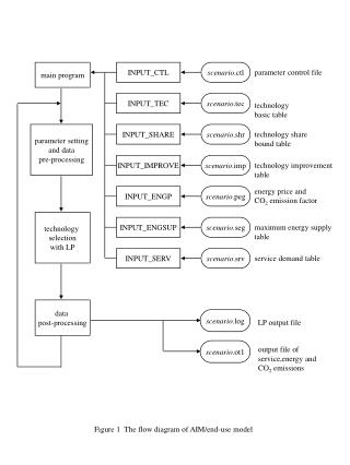
main program INPUT_CTL scenario.ctl parameter control file INPUT_TEC scenario.tec technology basic table parameter setting and data pre-processing INPUT_SHARE scenario.shr technology share bound table INPUT_IMPROVE scenario.imp technology improvement table energy price and CO2 emission factor INPUT_ENGP scenario.peg technology selection with LP INPUT_ENGSUP scenario.seg maximum energy supply table INPUT_SERV scenario.srv service demand table data post-processing scenario.log LP output file scenario.ot1 output file of service,energy and CO2 emissions Figure 1 The flow diagram of AIM/end-use model
Independent power generating device Heavy oil Hot water (OHW) (OLH) OCODE1,2 Generated electricity ZEL Gas Cooling device Cooling (GAS) (OAC) OCOOL1 Legends :external energy :service device :internal energy/service :final service Figure 2: The energy flow of example1
Share (%) Figure 3 An example of selecting service devices
CO2 emissions (ton C) Figure 4 An example of total CO2 emission
CO2 emissions (ton C) Figure 5 An example of CO2 emission by energy type
CO2 emissions (ton C) Figure 5 An example of CO2 emission by device type
Iron ore Sintering machine Limestone Sinter Molten steel Blast furnace Basic oxygen furnace Hot metal Coke Coal Coke oven Steel products Casting process Rolling Annealing furnace Coke quenching 1. The blast furnace process Steel products Electric arc furnace Casing and rolling Hot metal Scrap 2. The electric arc furnace process Iron ore Steel products Smelting reduction furnace Casing and rolling Hot metal Coal 3. The smelting reduction process Figure 7 Steel production processes
(COK) (ELI) (CEK) (COL) (YIR) STELE1 STUTL4 STUTL1 SSTCKF1,2 ZC1 ZCG ZCK STDIOS STCKD1,2 ZEC STELE3 STUTL2 ZST STSNT1 ZUT STUTL3 ISTBF1,2,3 ZBG ZMT ZEF STELE2 ZFG ISTOF1 ZST STELE4 ZEL ISTIN1,2 ZSP ISTRH2,4 ISTRH1,3 ZHS ISTAF1,2 STEEEE Hot rolled steel products Cold rolled steel products HSP CSP STELH1,2 (YSR) Figure 8 Structure of steel making processes
Flow control terminal STUTL1 Coke oven gas (ZCG) Flow control terminal STUTL2 Blast furnace gas (ZBG) UTILITY (ZUT) Heat for steam Flow control terminal STUTL3 Basic oxygen furnace (ZFG) Flow control terminal STUTL4 Purchased coke (COK) Power generation STELE2 Flow control terminal STELE1 Purchased electricity (ELI) Waste heat from coke quenching (ZEC) Power generation STELE3 ELECTRICITY (ZEL) Electricity Power generation STELE4 Waste heat from furnace (ZEF) Figure 9 Electricity (ELI,ZEL) and utility (ZUT) flows of the system