GBT Precision Telescope Control System
120 likes | 321 Vues
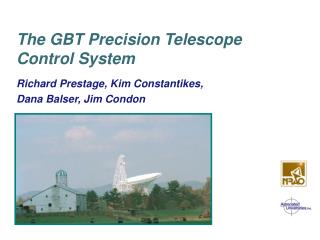
GBT Precision Telescope Control System. Kim Constantikes 4/8-9/03. What is the PTCS System?. PTCS is the integration of metrology components, servomechanisms, and estimators/controllers to precisely control the GBT optical elements. PTCS Components Servos Azimuth and elevation

GBT Precision Telescope Control System
E N D
Presentation Transcript
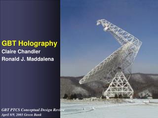
GBT Precision Telescope Control System Kim Constantikes 4/8-9/03
What is the PTCS System? • PTCS is the integration of metrology components, servomechanisms, and estimators/controllers to precisely control the GBT optical elements. • PTCS Components • Servos • Azimuth and elevation • Subreflector mount • Active surface • Receiver turret • Feed rotator • Tertiary
What is the PTCS System? (Cont) • Metrology • Laser rangefinders • Structural temperature sensors • Weather • Quadrant detector
PTCS Architecture • Engineering Measurement System (EMS) • GBT surveying tool • PMS algorithm test bed • Signal flow graph/graphical programming environment • Primarily for • Laser rangefinder data reduction • Explore/mitigate systematic errors • Precision Measurement System (PMS) • Production system for measurement of GBT optics, pointing • Uses all available data, e.g., LRF, inclinometers, etc. • Data irregularly sampled in time, outputs are predictions wrt time, elevation, temperature, wind… • Precision Control System (PCS) • Uses PMS data to control GBT elements • Configurable strategies, Various “optimal” configurations • Real time, fixed sample rates
PCS Alternatives • PCS is classical closed SISO loop control (single-input-single-output) • Loops in parallel are independent, e.g., 6 SR link actuators, azimuth “independent” of elevation • Nested control loops, e.g., LRF estimates of actual az/el versus encoder az/el. • Easy to visualize, but not optimal or optimality criteria not explicit • PCS is modern closed (multiple-input-multiple-output) loop control • Models interactions of subsystems, e.g., az-el coupling • Servo subsystems dynamics are closed loop controllers • Explicit optimality criteria • Explicit controllability/observability • Commanded scan is trajectory through GBT parameter space • Controller minimizes error/cost of actual versus commanded
PCS Alternatives, cont. • Open loop learned compensations • Individual subsystem control uses parametric or nonparametric corrections based upon offline measurements ,e.g., LRFs, or astronomical correlations with indirect measurements, e.g., defocused beam maps for primary figure, correlations with temperature, elevation, or pointing correction as a function of feed arm temperature/temperature gradient. • Have selected the classical approach for now • Easier to visualize, configure • Control tasks are not demanding: small and slow perturbations • No quantitative evidence that subsystem interactions are problematic, e.g. az/el coupling instabilities • Incremental approach more feasible • Estimation blocks can subsume approach 3.
Design Constraints • Legacy implementations unaffected as much as possible • ACU implementation will be effected • Objective to achieve scientific requirements in default observing mode • Architecture must accommodate a variety of observing scenarios • Scenario driven: Examples (See PTCS Observing Scenarios) • Engineering investigations • Fixed SR edge to Primary vertex distance Antenna configuration/characterization • Focus calibration Defocused beam mapping • Observing • Point source spectroscopy with double beamswitching via tertiary • OTF mapping with tertiary slewing
Paradigms • Strategies are contained in (and configured by): • Paraboloid shape as fcn of elevation: LUT, parametric… • Subreflector position/orientation as fcn of feed location and primary figure/location: LUT, parametric… • Mappings of total pointing error into subsystems: Functional, parametric… • External control and configuration: • Select strategies • Provide offsets from nominal positions (SUBTLE!) • Enable/inhibit control loops, pointing error mappings • Embedded optical model • Best estimates of actual pointing (control and OTF maps) • Eventually, best estimates of efficiency, beam shape, etc. • Nested and parallel SISO servocontrol • Simulate before implement- Simulate new strategies/configurations-Simulate-Simulate-Simulate…….
Additional Notes on Block Diagrams(See notes attached to diagrams also…) • Multiple SISO control subsystems implied • 6 identical link servos in subreflector control • Independent azimuth and elevation controllers • Blocks that allocate pointing errors to optical elements also implement a correction strategy • Subreflector pointing corrections as translation, rotation, or combination of both • Subreflector control block implements forward and inverse kinematic transforms • Main drive control block implements forward and inverse pointing model transformations • Parameter vector representations not yet fixed • Is pri node list? Parametric paraboloid? Surface-piston coordinates (u,v,w)?
Coordinates for tipping structure Optical Paraboloid vertex and plane of symmetry? Metrological Primary rim and feed arm tip? Needs to be relayable Topocentric Coordinates Virtual Az/El GBT Local frame (piers…) Global frames? Control Frames Subreflector forward/inverse kinematics Tertiary rotations Feed/turret/feed house… frames Primary surface and piston Coordinate Systems
Simulation • PCS must be simulated prior to implementation • Discover performance and stability issues • Make concrete decisions about sample rates, parameter sets • Subsystem models • May be able to resurrect RSI/PCD Simulink model of az/el • Simple models of SR link drives • Assumed tertiary design and performance • Use Simulink for simulation environment • Metrology models • Metrology and derived measurements not modeled • PCS estimator blocks have reasonable stochastic models of estimation error
Simulation, cont. • Completed simulation provides: • Template for implementation • Determines: • Sample rates • Estimation error requirements for performance • Parameters • Representations for built-in functions (e.g, primary shape) • Characterize performance over some environmental effects • Simulation may evolve to: • Test bed for PTCS configuration • Preplanning observations • Debugging implementations • Test bed for new algorithms • Evaluation of tertiary designs