Download
1 / 69
981 likes | 1.63k Vues
Blow Moulding Process & Barrier Containers Part 2 Equipment. Major process stages. Feeding system for the granules, regrind and masterbatches Melting and homogenizing of the plastic in a single screw extruder blowing of the bottle cooling of the bottle calibration and de-flashing

E N D
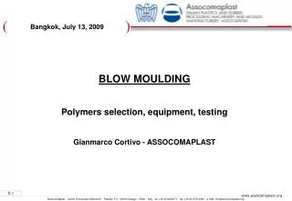
Blow Moulding Process & Barrier Containers Part 2 Equipment
Major process stages • Feeding system for the granules, regrind and masterbatches • Melting and homogenizing of the plastic in a single screw extruder • blowing of the bottle • cooling of the bottle • calibration and de-flashing • leak proof testing
Blow moulding techniques • Extrusion blow moulding • continuous extrusion • intermittent extrusion • Injection blow moulding • Injection stretch blow moulding
Continuous extrusion blow moulding 1 Line with double station for Max. 24 cavities
Blow Moulding Line Equipment elements • Feeding system (volumetric, gravimetric, mixing), hopper • Extruder: screw, barrel, adaptor • (Filter screen-pack, filter changer) • Head, parison control, die: mandrel, bushing • Parison cutter • Blow unit • Mould(s) • De-flashing unit • On-line test unit (holes, top-load) • Labelling (glueing, IML), printing (flaming, Corona)
Equipment set-up Die centeringadjustment bolts Die Blow pin Hot knife cutter Parison Mould
Blow Moulding Line – Extruder • Functions of the extruder: • - Convey the granules in the screw flight • Compress the solid granule and remove the air • Melt the granules • Mix the melt, to make it as homogeneous as possible • Produce the desired melt temperature • Produce the desired pressure to have the melt flowing
Blow Moulding Line – Extruder • Typical extruder for blow moulding lines • Normally with grooved barrel • 3 zone screw or barrier screw with or without mixing elements
L Metering zone Feeding zone zone Compression zone Connection to the motor D q F P H D Screw diameter L Screw length q Flight angle (17.65) P Pitch F Feeding zone depth H Metering zone depth A Feeding zone length/D C Compression z. depth/D M Metering z. length/D N Screw speed, rpm Screw
Screw • Typical 3-zone screw: • D= 90 mm L/D= 25 Compression ratio: 2.0 to 2.5 • Length feed section: 10D • Length compression section: 6D • Length metering section: 9D • Typical barrier screw with mixing head: • L/D: 20
Screw 3 Multi-Purpose Barrier Screw for Grooved Barrels
Mixing elements 2 Shear & mixing elements
Screw 3 Multi-Purpose Barrier Screw for Grooved Barrels
DISTRIBUTIVE (ananas, Saxton, Dulmage) Theydivideandrecombineflowstreams DISPERSIVE (UCC; cavity transfer mix, static mixer) Cutting strains generate the reduction of particles of immiscible components
Grooved barrel Grooved zone Cooling
Filters – Screen pack – Filter Changer old filter new filter
Types of dies • Spiders (PVC) • Mandrel • Spyral
Mandrel die • Low cost • Reduced external dimensions • High precision with annular die gap • Difficult centering • Long time needed for color change • Output depending
State-of-the-art structure of multilayer bottles 2 layers PE-LD/PE-HD 3 layers PET/PET/PET PET/PA/PET PE-HD/R PE-HD /PE-HD PE-HD/Adhesive/PA PE-HD/Adhesive/EVOH 4 layers PE-HD/R PE-HD/Adhesive/PA or EVOH
State-of-the-art structure of multilayer bottles 5 layers PE-HD/adhesive/EVOH/adhesive/PE-HD PE-HD r PP EVOH or PA 6 layers PE-HD/R PE-HD/adhesive/EVOH/adhesive/PE-HD PE-HD or PP EVOH or PA
Radial flow head – Heart shaped melt flow channels • Distance to exit on the back side of the mandrel • is shorter than the one of the extruder side = lower • pressure drop • - Reduces parison bending • Melt parted in two (180°) for optimized distribution • of thickness • - Fusion lines on the opposite part of entry
Die centering Die mandrel can be centered by means of adjustment bolds. Poor centering leads to uneven wall thickness distribution,resulting in poor bottle stiffness.
Die deformation • No flexibility • Used for containers with • special form (strong oval shape, • square)
Parison thickness control • Programming parison thickness • through electronic system to optimize • container wall thickness and • performance
Parison thickness control Vertical mandrel movements modify the die gap thus the parison thickness (and its swell)
Blowing systems • - Blowing is done aside of the die • Blowing pin descends in to the neck opening (continuous extrusion • lines, with or without neck calibration)
Blowing systems • Blowing pin is part of the mandrel (Uniloy equipments) intermittent, with neck calibration • Blowing pin replaced by a needle (carousel lines for aseptic containers or toys)
Blowing systems • Two blowing pins moving aside, used for flat articles with high widening • ratio. One of the pin is the blowing pin.
Blowing systems • Blowing air needs high pressure • Too high air pressure causes protrusions closed to the partition lines of • the mold • Too low pressure causes air trapping, rough surface and partition lines • not homogeneous • Pre-cooled air or liquid nitrogen can help reducing cycle time and • increasing production
Blowing systems • Pre-blowing with open parison • - avoids parison collapse • Pre-blowing with closed parison • - reduces parison elongation • - optimize mold filling • - improve formation of partition lines • (by reducing accumulation at the end • of the lines contributes to control • parison/container thickness • - reduce blowing time for large containers
Parison cut • Cold knives for HDPE (hot for PP) • Tear through head movements • (Uniloy lines and large containers) • Tear through mold movements
Moulds • Manufactured using aluminum alloys with high heat transfer • Inserts for de-flashing made of steel with low abrasion coefficient
Moulds 3 • Mould movements • normally the mould moves aside of the die to avoid the descending • parison stitching on the mould