Download
1 / 19
190 likes | 337 Vues
Beam Interlocks for Detectors and Movable Devices. J. Wenninger AB-OP-SPS for the LHC Machine Protection WG. Reminder on the LHC Interlock System (LEADE 18.10.2004). Safe LHC Paramters & their distribution. Preliminary ideas on Interlocks for detectors & movable devices.

E N D
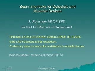
Beam Interlocks for Detectors and Movable Devices J. Wenninger AB-OP-SPS for the LHC Machine Protection WG • Reminder on the LHC Interlock System (LEADE 18.10.2004). • Safe LHC Paramters & their distribution. • Preliminary ideas on Interlocks for detectors & movable devices. • Technical drawings : courtesy of B. Puccio (AB-CO) J. Wenninger / LEADE
Beam Interlock System : aims and objectives The primary aim of the LHC beam interlock system is to provide a failsafe & high reliability link between users requesting a beam abort and the beam dumping system. In addition it is linked to the SPS extraction system to permit/inhibit beam injection. • Two roles: 1) Allow injection when ALL user systems are ready for beam. 2) Transmit any beam dump request from user systems to the Beam Dumping system. • Additional objectives: • Protect the beam • Faulty trigger signals should be avoided. • Provide post-mortem information • For multiple alarms: identify the initial failure & given time sequence. J. Wenninger / LEADE
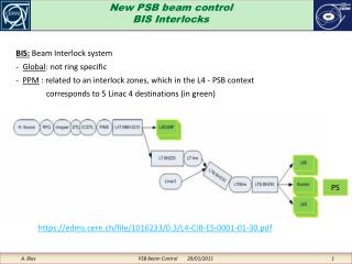
LHC protection systems USER_PERMIT SIGNALS BEAM_PERMIT STATUS SIGNALS User System #10 User System #8 User System #1 User System#16 User System #9 User System #2 LHC Injection System for beam 1 BEAM1_PERMIT Beam Dumping System for beam 1 UNMASKABLE INPUTS SPS Extraction System for beam 1 PM event Trigger Timing System LHC Injection System BEAM INTERLOCK SYSTEM for beam 2 BEAM2_PERMIT Beam Dumping System MASKABLE INPUTS for beam 2 SPS Extraction System for beam 2 to User Systems Mask Settings Safe Beam Flag Principle of the Beam Interlock System J. Wenninger / LEADE
Distributed architecture Clients are connected to the BIC modules J. Wenninger / LEADE
Beam Permit status signal • The BEAM_PERMIT carried by the Intk loop can be: • TRUE(beam operation is permitted) • Injection of beam is allowed. • Beam operation continues. • FALSE(beam operation is NOT permitted) • Beam injection and SPS extraction are blocked. • If beam is circulating and the BEAM_PERMIT changes from TRUEto FALSE, then the beam will be extracted to the dump. • There is one BEAM_PERMIT for each beam. • Distribution via hardware links to: • Beam Dumping System • LHC injection kickers • SPS Extraction systems • Beam interlock user systems. J. Wenninger / LEADE
Beam abort and inhibit • Any system connected to the beam interlock system that : • wants to abort the beam, • is not ready for beam ( beam inhibit), must send an interlock (remove its USER_permit signal) in order to remove the beam permit. J. Wenninger / LEADE
Safe LHC Parameters There are a number of highly critical pieces of information that must be distributed to machine systems around the ring (beam loss monitoring, BIC, beam dumping system…). Presently : • Energy (obtained from main bends currents). • Flag to indicate the presence of beam (I > 109 p). • Flag to indicate that the beam is safe (I < 1012 p at injection). • Under discussion : machine mode (injection, ramp, stable beams…). SLPs (Safe LHC Parameters) It is not yet clear how/if information on the collimators is added to the list. Other candidates are the beam intensities. Note that this system is reserved for CRITICAL parameters. Besides a safe transmission we also have the (at least as critical) issue of a safe generation ! J. Wenninger / LEADE
typical “Timing” message: 1st byte P 2nd byte P 3rd byte P 4th byte P Starting Seq. Ending Seq. SLP distribution Present idea for the SLP distribution : • Re-use hardware from the (millisecond) machine timing system: reliable transmission system, based on VME standard. • Speed / bandwidth : 512Kbits and 1ms rate. • Easy to re-use Generator and Receptor electronics. • Multi-byte format: possible extension for additional parameters. • Main users will be chained in a loop – with possibility to add ‘star’ users. • Error checking at the end of the loop (with possibility for beam dump). J. Wenninger / LEADE
RCV RCV RCV T T T T T T S S S B B B E E E Ring and star distribution for additional user Fiber optic Fiber optic BLM crate in SR8 to IR1 from IR7 IR8 BIC crate in UA87 BIC crate in UA83 J. Wenninger / LEADE
Software interlock system • In addition to the (fast) Hardware Beam Interlock System, the LHC will also have a Software Interlock System : • not failsafe, • but much more flexible. • reaction times ~ many milliseconds to seconds. • (much) more complex interlock logic. • it will be able to : • dump beam (input to the beam interlock system), • inhibit extraction from the SPS (input to SPS extraction system), • cut beam already in booster (message to Master Timing Generators). • This system will be developed for the SPS and the LHC. To be tested in 2006 at the SPS (present SPS system not up to the job for the future). J. Wenninger / LEADE
Experiments • Each experiment can provide user input signals to the beam interlock system : • Background / radiation interlock. • Movable device interlock (VELO, RPs). • This user signal must be used to : • Inhibit injection / SPS extraction if the detector is not ready for beam. • Request a beam dump if radiation levels, rates… are so high that the detector may be damaged. • Request a beam dump in case of incorrect positioning of movable devices. • In addition, software interlocks could / should be generated. • The discussion on interlocking of spectrometers magnets will be done by the MPWG directly with PH/DT1 (coming soon) – independent interlock. Separate signals if possible ? J. Wenninger / LEADE
Backgrounds, calibration, spectrometers • In case of unacceptable ( possible damage) background or radiation : • Set a HW interlock to dump beams. • Detector calibration (between fills) : • Set a HW interlock to dump / prevent injection. • Set a software interlock to stop injection – provides information on WHY the beam is stopped. J. Wenninger / LEADE
Operation of movable devices • Of concern here : roman pots & VELO. • Movable devices should only leave their ‘OUT’ position with ‘stable beams’ : • Beams are ramped & squeezed @ physics energy. • Beam parameters are OK according to C3. • Collimators and absorbers in position. • … Please note that stable beams does NOT mean that we will not continue tuning the beams, collimators…. Failures leading to a beam dump within 3 turns are always possible. • Beams should be dumped / not injected if a movable device is not ‘OUT’ and the above conditions are not true. J. Wenninger / LEADE
Roman pots • Roman pots are special since they can ‘compete’ with the collimators in terms of beam scrapping – must ensure they stay in the shadow of the collimators. • Proposal 1 (strongly encouraged by collimation WG) : • Motors and control of roman pots are identical (or fully compatible) to collimator system. • RPs, collimators and absorbers are controlled from a single place to ensure fully consistent positions. • Generation of interlocks is taken care by collimator control system. • Proposal 2 : • RP control must be a ‘slave’ of the collimation control system that dictates position ranges and gives green light for movements. • Proper interlock generation is under the responsibility of experiment. J. Wenninger / LEADE
Movable devices : conditions • Interlock proposal for VELO / RPs not under machine control : • The safe conditions for moving devices is encoded in a bit/word that is part of the SLPs and distributed to the concerned experiments. • The following interlock condition must be applied : • Device out : no interlock, beam OK. • Device in + safe conditions : no interlock, beam OK. • Device in + unsafe conditions : interlock, beam dump. • ‘Normal’ movements should only be allowed when conditions are safe. • For movements during access, tests… (i.e. unsafe conditions) an interlock must be set. • A additional software interlock should be generated to inhibit extraction from the SPS. J. Wenninger / LEADE
Outlook It’s just the beginning of the discussions ! J. Wenninger / LEADE
LHCb / ALICE special from SPS operation • In parallel to LHC running, the SPS will be running LHC beams without injection into the LHC : • Maintain and improve beam quality. • Verify steering and beam quality in the long transfer lines TI2 / TI8. • A full test of the beam in the SPS down the last dump in front of the LHC injection elements will be required before EVERY LHC filling sequence is started. • LHC beam tests of the transfer line imply that muons will be generated in the dump blocks near the LHC tunnel. Those muons fly into the LHCb and ALICE caverns. We have to look in more detail at the operation of the lines to understand how much beam can be send down the lines and under which conditions. • Line operation impossible during LHC physics runs ? • What about detector calibrations… between runs ? • … J. Wenninger / LEADE
USER_PERMIT signal changes from TRUE to FALSE a failure has been detected… User System process Signals send to LBDS Beam Interlock system process Kicker fired all bunches have been extracted ~70μs max. ~ 89μs > 10μs t1 t2 t4 Achievable response time ranges between 100 s and 270 s (between the detection of a beam dump request and the completion of a beam dump) Time between a Request to a Beam Dump beam dump request Beam Dumping System waiting for beam gap 89μs max time t3 J. Wenninger / LEADE
to Beam Interlock Crate From User System Beam Interlock User Interface • Receives the USER_PERMIT from a given LHC system. • Transmits the USER_PERMIT to the BIC crate. • Some User Systems will always provide the USER_PERMIT for both beams. If failure both beams will be dumped. • Some User Systems will dump either Beam 1 or Beam 2. • The BEAM_PERMIT status for each beam is provided to theUser System. J. Wenninger / LEADE