New PSB beam control BIS Interlocks
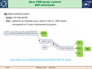
BIS: Beam Interlock system - Global : not ring specific PPM : related to an interlock zones, which in the L4 - PSB context corresponds to 5 Linac 4 destinations (in green). New PSB beam control BIS Interlocks. PS.

New PSB beam control BIS Interlocks
E N D
Presentation Transcript
BIS: Beam Interlock system • - Global: not ring specific • PPM : related to an interlock zones, which in the L4 - PSB context • corresponds to 5 Linac 4 destinations (in green) New PSB beam controlBIS Interlocks PS https://edms.cern.ch/file/1016233/0.3/L4-CIB-ES-0001-01-30.pdf PSB Beam Control 20/01/2011
This “Beam Permit” will be used as an interlock to all 4 rf Beam controls => stop acceleration on 4 rings The BIC signal is PPM (destination related!) One cycle for ISOLDE might be OK when the next towards PS is not or vice-versa. New PSB beam controlBIS Interlocks Our input to the BIS https://edms.cern.ch/file/1016233/0.3/L4-CIB-ES-0001-01-30.pdf PSB Beam Control 20/01/2011
Up to 14 CIBUS connected to one BIC Here we need to create 2 redundant signals (and cables) to indicate a global rf fault New PSB beam controlBIS Interlocks Here we are also ! https://edms.cern.ch/file/636589/1.5/CIBU-User-Manual-1v5.pdf PSB Beam Control 20/01/2011
We will have one of these modules for the RF-LL to propagate our interlock We will only feed the CIBUS input with a redundant ( 2channels) “all rf down” signal New PSB beam controlBIS Interlocks https://edms.cern.ch/file/636589/1.5/CIBU-User-Manual-1v5.pdf PSB Beam Control 20/01/2011
New PSB beam controlBIS Interlocks https://edms.cern.ch/file/636589/1.5/CIBU-User-Manual-1v5.pdf PSB Beam Control 20/01/2011
USER_PERMIT is guaranteed FALSE when the diff. voltage < 0.7 V and guaranteed TRUE when > 3V (with courant limited to 12 mA) New PSB beam controlBIS Interlocks https://edms.cern.ch/file/636589/1.5/CIBU-User-Manual-1v5.pdf PSB Beam Control 20/01/2011
This CIBUS “beam info” output is of no interest to us It is only a logic function of a limited number of “user permit” values Output available on the CIBUS for local use New PSB beam controlBIS Interlocks https://edms.cern.ch/file/636589/1.5/CIBU-User-Manual-1v5.pdf PSB Beam Control 20/01/2011
New PSB beam controlBIS Interlocks CIBUS Burndy Connector from/to User https://edms.cern.ch/file/636589/1.5/CIBU-User-Manual-1v5.pdf PSB Beam Control 20/01/2011
New PSB beam controlBIS Interlocks https://edms.cern.ch/file/636589/1.5/CIBU-User-Manual-1v5.pdf PSB Beam Control 20/01/2011
New PSB beam controlBIS Interlocks https://edms.cern.ch/file/636589/1.5/CIBU-User-Manual-1v5.pdf PSB Beam Control 20/01/2011
The BIS interlock is global – all 4 rings – In the “BEAM INTERLOCK SPECIFICATIONS FOR LINAC4, TRANSFER LINES AND PS BOOSTER WITH LINAC4” document https://edms.cern.ch/file/1016233/0.3/L4-CIB-ES-0001-01-30.pdf These are referred to as external conditions with name BR1->4.RF N.B.: there are other pieces of information called external conditions (see next slides) New PSB beam controlInterlocks The ring specific interlockindicates, to the Chopper mainly, but not to the BIS that a specific ring is not available for acceleration PSB Beam Control 20/01/2011
4 different interlock signals per ring have been considered to input the RF (each may trigger a different response from the rf). 1) Interlock from the BIS (PPM, synchronous with the cycle, all rings) 2) Interlock due to external conditions (PPM, synchronous with the cycle, ring specific) 3) Interlock due to a real time measurement (ring specific, response time in the order of a couple of ms) 4) Interlock from the RF power equipment (real time “over current” + “gap closed” +... for each of the up-to-3-per-ring cavities) New PSB beam controlInterlocks Interlocks 2) and 4) will have to be analyzed to create a ring specific interlock (or external condition) to be sent to the Chopper. Ex: if for a ISOLDE cycle the C16 cavity is not ready, the cycle should still remain => not ring specific interlock PSB Beam Control 20/01/2011
1) The BIS signal will be activated as a result of upstream detected faults. The list of these faults is out of the scope of this presentation. Source: BIC of the chopper-pre-chopper chain, located in the Linac 4 building. Signal and type of media: pair of opticalfibbers (for connectors and cables see annex) RF response to the interlock: For the time being the action will be: rf voltage brought to zero volt and rf frequency brought to injection value. Contact person: Bruno + Bettina + José New PSB beam controlInterlocks PSB Beam Control 20/01/2011
2) Interlock signal due to external conditions (ex: experiment not requiring anymore the beam) Source: Software chain ending on a CTRV within the RF VME/VXS crate Signal type: TTL-bar timing pulse with an appropriate (programmable) length to be defined. The C-time occurrence value within the interlocked cycle needs to be defined to suit the RF DSP process. RF response to the interlock: For the time being the action will be: rf voltage brought to zero volt and rf frequency brought to injection value. Contact person: Ioan Kozsar + Bettina + José New PSB beam controlInterlocks PSB Beam Control 20/01/2011
Interlock due to real time beam current measurements: All the 4 beam currents are sampled at a specific C-time (programmable? to be decided by OP). If the specified ppm current-threshold, for a given ring is exceeded, an rf interlock is sent to the specified ring. We have first planned to use a CTRV TTL-bar output as the source of the interlock signal, but Lars Jensen and Ioan are now proposing, to simplify the integration, to use a simple VMOD TTL (still the standard to use for this kind of application, according to Javier Serrano). Source: DPSBBDR, bât 361, R758, very close to the rf cage (<10 m). The general idea (Ioan) is that the ADCs measuring the 4 beam intensities should be within the BI group crates where the beam transformer signals are available. A sample of the beam current value at a specific time value within the cycle should then possibly propagate an interlock within a couple of ms. This necessitates that the VMOD TTL creating the TTL-bar interlock pulse for each of the 4 rings sits in the same crate as the ADCs. Signal type: TTL-bar bit from a VMOD TTL on a line to be defined (high level means OK). RF response to the interlock: For the time being the action will be: rf voltage brought to zero volt and rf frequency brought to injection value. Contact person: Lars Soby (BI), Ioan for the control aspect, Lars Jensen for the Fesa class update of the BCTs, José for the software and Bettina for the overall view. New PSB beam controlInterlocks PSB Beam Control 20/01/2011
4) Interlock from the RF power equipment Source: BRF Signal type: Multiplexed information on a single fibber for each cavity. An electronic module on the power side will collect all the error bits and combine the information on a single link. The idea is that the time information remains present on the link with a precision in the order of 1 ms This means that, if an over-current lasts 20 ms for example, this 20 ms value should be decoded on the LL side (communication protocol to be defined) RF response to the interlock: the LL RF will abort the acceleration (rf voltage brought to zero volt and rf frequency to injection value) Moreover if 10ms before injection, all the cavities selected by the operation are not ready, the faulty ring injection will be cancelled at the Chopper stage in real time (details to be discussed with Ioan and Philippe). Contact person: Philippe, Ioan, Bettina, José New PSB beam controlInterlocks PSB Beam Control 20/01/2011
Still under discussion: Ring specific interlocks to the chopper. From the RF-LL side there is no way to know if a cavity is strictly required for a specific user. A fault on 1 or 2 cavities doesn’t necessarily mean that the cycle needs to be cancelled! The OP needs to decide if they are willing to send us a mask of required cavities for each cycle. Ring specific interlock hardware: to be discussed with Philippe Communication protocol and hardware between Power RF and LL New PSB beam controlInterlocks PSB Beam Control 20/01/2011
Possible implementation New PSB beam controlInterlocks VD 80 : https://wikis.cern.ch/display/HT/VD80+-+16+channels%2C+200kSPS+16bits SCL description: \\cern.ch\dfs\Departments\AB\Groups\RF\Machines\General\Documentation\ElectronicDesignDocumentationOverview.pdf PSB Beam Control 20/01/2011
New PSB beam controlInterlocks (Annex) https://edms.cern.ch/cedar/plsql/doc.info?cookie=9990573&document_id=1106006&version=1&p_tab=TAB1 PSB Beam Control 20/01/2011
New PSB beam controlInterlocks (Annex) https://edms.cern.ch/cedar/plsql/doc.info?cookie=9990573&document_id=1106006&version=1&p_tab=TAB1 PSB Beam Control 20/01/2011
New PSB beam controlInterlocks (Annex) https://edms.cern.ch/cedar/plsql/doc.info?cookie=9990573&document_id=1106006&version=1&p_tab=TAB1 PSB Beam Control 20/01/2011
New PSB beam controlInterlocks (Annex) https://edms.cern.ch/cedar/plsql/doc.info?cookie=9990573&document_id=1106006&version=1&p_tab=TAB1 PSB Beam Control 20/01/2011
New PSB beam controlInterlocks (Annex) https://edms.cern.ch/cedar/plsql/doc.info?cookie=9990573&document_id=1106006&version=1&p_tab=TAB1 PSB Beam Control 20/01/2011
Proposed solutions for the Beam permit reception New PSB beam controlInterlocks (Annex) https://edms.cern.ch/cedar/plsql/doc.info?cookie=9990573&document_id=1106006&version=1&p_tab=TAB1 PSB Beam Control 20/01/2011