New PSB Beam Control
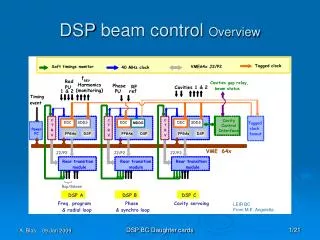
Clock distribution Motherboard to daughter cards connectors Daughter cards front panel. New PSB Beam Control . Present clock signal: Pulse width modulated Tag at each revolution Double tag when required for a synchronous loading of parameter within the daughter cards.

New PSB Beam Control
E N D
Presentation Transcript
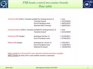
Clock distribution Motherboard to daughter cards connectors Daughter cards front panel New PSB Beam Control Working group meeting 27/08/2009
Present clock signal: • Pulse width modulated • Tag at each revolution • Double tag when required for a synchronous loading of parameter within the daughter cards New PSB Beam Control Clock Signal • Required analogue BW > 830 MHz (to include 3rd harmonic) • Required equivalent digital throughput >280 Mb/s • 50% duty cycle clock required by the ADCs and DACs of daughter cards. • Divide clock by 2 • 80 MHz max sampling rate of ADCs => Fclock MDDS up to 160 MHz Working group meeting 27/08/2009
Tagged clock on a single differential twisted line: • Pro: • Makes use of a single differential twisted pair - a simple coaxial line could be also used • Cons: • Requires a “non-FPGA- implemented” tagging and de-tagging circuit • Necessitates a doubling of the clock frequency (to allow getting a 50% duty cycle sampling clock with a simple divide-by-2 circuit) • Sampling limited to a practical 80 Ms/s (creation and decoding of a < 1.8 ns pulse) New PSB Beam Control Proposed Clock signal Working group meeting 27/08/2009
New PSB Beam Control Clock Decoding and dividing Circuit Could be avoided ! Working group meeting 27/08/2009
Tagged clock on a pair of twisted lines: • Pros: • Easy to create and decode in a FPGA (no external circuit required due to lowered timing constraints) • Improved sampling frequency limit (200 MHz and more) • With limited modifications on the daughter cards, the present hardware can be made compatible. • Easier to monitor (trigger on the tag). • Lower bandwidth requirements (240 MHz or 80 Mb/s with the present sampling rate) • Cons: • Makes use of two twisted lines • Maximum skew needs to be specified New PSB Beam Control Proposed Clock signal Working group meeting 27/08/2009
Tagged clock on a pair of twisted lines: With an improved maximum sampling frequency of 100 MHz (80 MHz presently) the tolerance in terms of skew is as follow: At the emitting end (FPGA) and Receiving end (FPGA), the skew can be controlled within 100 ps? The propagation time within New PSB Beam Control Proposed Clock signal Working group meeting 27/08/2009
New PSB Beam Control Proposed Clock signal Working group meeting 27/08/2009
Maximum clock connector’s width: Daughter card width (where the front panel connectors are placed) = 84 mm Requirements in terms of connectors: MDDS : 1 clock output (2 presently) + one 10 MHz SMC input DDC: 1 clock input + 4 SMC inputs SDDS: 1 clock input + 4 SMC outputs SMC connector width = 7mm Space between SMC and PCB limit = 4mm Space between SMCs = 7mm Space between SMC and Clock connector = 5 mm Space between clock connector and PCB limit = 4 mm On the DDC and SDDS, when all 4 SMC connectors are paced, there is 22 mm left for the clock connector = 84 - 4x7 - 3x7 - 4 - 5 - 4 This 22 mm value is compatible with a double clock output connector on the MDDS New PSB Beam Control Clock connector dimensional requirements Working group meeting 27/08/2009
Second constraint for the clock connector width: • The VME clock fan-out module is conveniently designed with 1 input and 9 outputs on a single U front panel. • Space available between 2 VME front panel holder on the PCB = 214 mm • Space between connectors = 4 mm (5 mm presently) • Room for 1 LED (clock active) = 14 mm • Space between VME FP fixing and connector = 3 mm • There is 160 mm left which means 16 mm left for each clock connector width = (214 - 9x4 - 14 - 3) / 10 • Some options to relax the constraints in term of width: • Extension of the VME front panel width to 2U - VME spare slots can be an issue for future implementations (PS ?) • Distribution of the clock to the daughter cards from the Motherboard single clock connector for each motherboard only 5 connectors on the VME clock fan-out. • Using block of connectors sometimes supplied by manufactures (ex RJ45 blocks) which diminishes the need for inter-connectors space New PSB Beam Control Clock connector dimensional requirements Working group meeting 27/08/2009
Maximum connector’s height: With a double width (2U)VME front panel tied to the mother board, the space between the motherboard PCB and the front panel edge is 34 mm. These 34 mm are shared by: The motherboard-to-daughter card connector = 7mm The daughter card PCB thickness = 2mm The rf shielding gasket support = 2 mm Front-panel remaining metal from connector to edge = 3mm (can be less) There is 20 mm left for the clock connector height = 34 - 7 - 2 - 2 - 3 Summary: The clock connector should be less than 16 mm wide (with some possibilities for 20mm) and less than 20 mm high New PSB Beam Control Clock connector dimensional requirements Working group meeting 27/08/2009
What we have presently: • IEEE-1394b-2002 or FireWire 800, 9 pin connector • Rigid cable causes bending forces on the board and therefore detachment of the connector (short “legs” do not go through the board) • Standard defined for up to 800 Mb/s per twisted pair (2 pairs) • Width 12 mm and height 9 mm compatible with requirements New PSB Beam Control Current Clock physical media : 1394b Information below from IEEE: http://ieeexplore.ieee.org/stamp/stamp.jsp?tp=&arnumber=1146719&isnumber=25840 A signal pairs attenuation requirement applies only to the two signal pairs for any given cable assembly. The connector allowance listed in table 4-11W is for two mated connectors, one at the assembly input and one at the output Working group meeting 27/08/2009
New PSB Beam Control Current Clock physical media : 1394b Working group meeting 27/08/2009
New PSB Beam Control Current Clock physical media : 1394b Working group meeting 27/08/2009
New PSB Beam Control Current Clock physical media : 1394b Working group meeting 27/08/2009
New PSB Beam Control Current Clock physical media : 1394b Working group meeting 27/08/2009
Molex IEEE1394B cable assembly (1 to 4.5 meters length) Part number 0687690027 New PSB Beam Control Current Clock physical media : 1394b Working group meeting 27/08/2009
Alternative connecting standards are available on the market for fast digital signaling. They are well suited to our clock distribution requirements. • 2 good candidates are: • Gigabit or 10gigabit standards using RJ45 connectors • e-sata New PSB Beam Control Alternative Clock physical media Working group meeting 27/08/2009
eSATA • 3Gb/s, 2 times faster than 1394b (1600). • 2 differential pairs (Tx and Rx) + 3 ground pins. • Withstands yanking and wiggling. New PSB Beam Control Alternative Clock physical media : eSATA Mechanical characteristics: Mating force max. 20N Un-mating force 4 N min. (1394b has 10 N min.) Durability 2500 cycles • Worries? • Cable a bit stiff because it is flat • Wide connector (21mm) • 2 twisted pairs • Length limited to 2 meters Working group meeting 27/08/2009
Molex eSATA cable assembly (1 to 2 meters length) Part number 0687820002 New PSB Beam Control Alternative Clock physical media : eSATA 8dB/2m Working group meeting 27/08/2009
Ethernet standard IEEE 802.3 • 4 differential pairs • Excellent availability • Solid PCB fixing • PSB socket width a bit above specifications (17 mm instead of 16, but still feasible) RJ-45 modular jack and male connector New PSB Beam Control Alternative Clock physical media : IEEE 802.3 using RJ45 Mechanical characteristics: Mating/un-mating forces ~ 22 N max. Durability 1000 cycles Working group meeting 27/08/2009
1000BASE-T standard IEEE 802.3ab under standard 802.3-2005 New PSB Beam Control Alternative Clock physical media : IEEE 802.3 using RJ45 • For copper wire 1000BASE-T topology or 10GBASE-T topology should be used, others are specified for fibers. • These standards are using cat 5, cat 6 and cat 7 cables frequently terminated using RJ-45 jacks according to the TIA/EIA-568-B standard for pin/pair assignments (see further slides). Working group meeting 27/08/2009
Gigabit Ethernet crossover connection (all four pairs crossed): New PSB Beam Control Alternative Clock physical media : IEEE 802.3 using RJ45 Working group meeting 27/08/2009
Pin assignments as stated in IEEE 802 standard: New PSB Beam Control Alternative Clock physical media : IEEE 802.3 using RJ45 RJ-45 connector consists of 4 differential pairs. If we terminate STP cable with RJ-45 connector, cable shielding will be connected to metal shell (compare the transparent plastic cover and metal). When using separate ground spring modular jack connector, shielding can be grounded to the circuit board ground. Working group meeting 27/08/2009
8P8C (RJ-45) connector New PSB Beam Control Alternative Clock physical media : IEEE 802.3 using RJ45 • Entire connector is covered with metal shell. • Metal shell is separated from ground spring connected to cable shielding. • Ground spring will be connected to RJ-45 male connector’s shielding as they are plugged. • Connector is TM24RSG-5A-88 from Hirose Working group meeting 27/08/2009
RJ-45 eSATA 1394b 9-pin New PSB Beam Control Alternative Clock physical media : IEEE 802.3 using RJ45 Working group meeting 27/08/2009
Conclusion: 1394b (presently in use), eSATA and Gigabit Ethernet (with RJ45) are defining cables and connectors characteristics (well) above our requirements. 1394b has the great advantage of being in place and has the smallest overall size… but requires some caution concerning the fragile PCB connector (Front panel suggested) RJ45 has all the advantages except size (although it can be dealt with) eSATA is a good candidate but its size doesn’t allow its installation on the Daughter cards. New PSB Beam Control Clock distribution Our Preference: Using the clock tagging on 2 lines. As there is no crucial reason for having the clock connector on the daughter card: Supply the clock from the Mother-Board (divides by 2 the number of clock cables per crate) If a clock distribution from the mother board is accepted, the connector can be freely chosen (and dropped on the VME front panel or Rear transition module tested up to 1Gb/s by John) In this context, RJ45 has the best overall advantages (Good BW, 4 lines instead of 2, not supply problem). eSATA though would be compatible with the selected (by John) inter-motherboards serial communication (although they could also use RJ45) Working group meeting 27/08/2009
What do we need? • Stack height min. 7 mm • Throughput :100Mb/s per pin • Nb of pins 140 (70 signal + 70 ground) • Conan • Our current connector • 9 – 69 pins • stack height 4.15 -7 mm • Best availability from FCI New PSB Beam Control Daughter-card to motherboard inter-connection Bergstak 40 – 200 pins Stack heights 5 – 16 mm MEG-array 81-528 pins Stack heights 4 – 14 mm 10Gb/s per diff. pair Working group meeting 27/08/2009
PMC: PCI Mezzanine Card standard (IEEE 1386) This is a well known standard in the industry, which is currently intensively used. It belongs to a general standard family called CMC (Common Mezzanine Card) Is compatible with many different carrier board formats: VME, VME64, VME64x, Multibus, CompactPCI,… PMC boards can use less than 4 connectors when necessary, while occupying the missing connector area with components. Connectors used: EIA-700 AAAB (i.e. Molex 71436 and 71439 http://www.molex.com/pdm_docs/ps/PS-71436-9999.pdf) New PSB Beam Control Daughter-card to motherboard inter-connection Working group meeting 27/08/2009
FMC (VITA 57) This industrial standard is becoming very popular and is planned to be used in BE-CO and BE-BI. There 2 types of mezzanine connectors: Low Pin Count (LPC) connector with 160 pins High Pin Count (HPC) connector with 400 pins. A daughter card with the LPC connector can mate with a carrier that utilizes either an LPC or HPC connector. HPC on the motherboard will support the widest range of future daughter cards. HPC: 400 I/Os in a 40 x 10 array, 8.5mm and 10mm stack heights Connector series is called Searay Thorough testing already made by Samtec, fulfills our constraints, 2.5Gb/s / pair Low insertion/extraction forces, 50g max. per contact (FCI Conan 125g) Cable mates available up to 558.8mm Many manufacturers (e.g. Samtec and Molex) New PSB Beam Control Daughter-card to motherboard inter-connection Working group meeting 27/08/2009
Conclusion: • The Vita 57 standard connectors is our favorite choice. • Many electronic manufacturers develop boards using this standard. • High frequency specifications: 2.5 Gb/s • We will share this standard with the BI and CO groups New PSB Beam Control Daughter-card to motherboard inter-connection Working group meeting 27/08/2009
Although daughter cards have been used until now, without any front panel, • there are reasons to envisage their implementation: • Lower constraints on the motherboard to daughter card connector • Better EMC • Better air cooling • Lower air cooling noise New PSB Beam Control Daughter card front panel The depicted standard, specified by Vita 57, might be to small for our needs. Something equivalent could nevertheless be designed. Working group meeting 27/08/2009
Tagging scheme on 2 lines instead of 1: This means only hardware simplification and increase in performances Motherboard to daughter card connector: Vita 57 is a modern standard used by other groups (no spare parts problems) Daughter-cards front panel: Good benefits and only additional mechanics Clock from motherboard: Single cable for each DSP board lower needs for Fan-out, single detagging circuit (although not necessary with the clock on 2 lines, wider range of choices for the clock connector (RJ45) on the motherboard front panel or on the rear transition module (VME P2 connector tested up to 1 Gb/s by John Molendijk: VME board P2 VME board P2 VME board) New PSB Beam Control Overall Conclusion Working group meeting 27/08/2009
Cable specifications New PSB Beam Control Annex Working group meeting 27/08/2009
Networking cable categories and standard specifications: New PSB Beam Control TIA/EIA-568-B Category 6A is rated up to 500MHz, 1Gbps, in the standard. We’ve used it in the LHC Beam Control System for baseband SerDescomms up to 1.5 Gbps per pair, for distances not bigger than 3 meters. Category 7A is rated up to 1GHz, 10Gbps. It has better crosstalk characteristics than Category 6A. Working group meeting 27/08/2009
Performance comparison at 100MHz (100 meter length): New PSB Beam Control TIA/EIA-568-B This is what the standard demands. Commercially available cables, offer better performances. Working group meeting 27/08/2009
Dätwyler Cables UNINET 6702 4P SF/UTP AWG24 cable for Category 5e / 6 Category used in the LHC Beam Control for SerDesComms at 1.5Gbps in baseband. Delay Skew: 25 ns/100m New PSB Beam Control TIA/EIA-568-B Attenuation and NEXT for 100 meter length: Working group meeting 27/08/2009
Dätwyler Cables UNINET 7702 flex 4P S/FTP cable for Category 6/Ea Bandwidth up to 1.2GHz Already tested in the lab with the SerDes baseband 1.5Gbps comms channel up to 3.25 meters. Delay Skew: 4 ns/100m New PSB Beam Control TIA/EIA-568-B Specifications for 10 meter length: Working group meeting 27/08/2009
SIEMON TERA 1000MHz cable Category 7 S/FTP Specifications for 100 meter length: New PSB Beam Control TIA/EIA-568-B Working group meeting 27/08/2009
Cable relevant characteristics summary: New PSB Beam Control TIA/EIA-568-B summary Commercially available patch-cords made with the described cables. Connections: straight and crossover. Lengths: from 0.1 up to 20 meters. Different colors. Working group meeting 27/08/2009
Summarizing the different standards and cables shown: New PSB Beam Control Standards comparison The best results for long distances and for applications where crosstalk Isolation is critical limiting factor, are for the EIA-568B cable. The IEEE1394 has good attenuation characteristics, but has a weakness on the connector mechanics (unless using a front-panel on the daughtercard). eSATA is a good candidate, as seems mechanically stronger than the actual Firewire connector, and has good bandwidth. However its size makes it (like RJ45) difficult to be integrated in the daugthercard. Working group meeting 27/08/2009