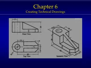
Chapter 6 Assembly Drawings
Chapter 6 Assembly Drawings. Topics Exercises. Assembly : Topics. Summary 6.1) Definitions 6.2) Views Used in Assembly Drawings 6.3) Things to Include/Not Include 6.4) Standard Parts - Specifications for General Fasteners

Chapter 6 Assembly Drawings
E N D
Presentation Transcript
Chapter 6Assembly Drawings Topics Exercises
Assembly : Topics Summary 6.1) Definitions 6.2) Views Used in Assembly Drawings 6.3) Things to Include/Not Include 6.4) Standard Parts - Specifications for General Fasteners - Specifications for Bolts and Nuts (Advanced Topic)
Assembly: Exercises Exercise 6-1: Section lines in assemblies Exercise 6-2: Working drawing package 1 Exercise 6-3: Working drawing package 2 (advanced exercise)
Assembly Drawings Summary
Summary • What will we learn in Chapter 6? • How to create an assembly drawing. • How to create a standard parts sheet. • Key Points. • Assembly drawings show how individual parts fit together to make a machine. • A standard parts sheet contains purchased items.
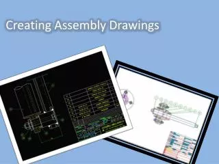
Assembly Drawings 6.1) Definitions
Assembly Drawing • What is an assembly drawing and why do we need them? An assembly drawing is a drawing of an entire machine or system with all of its components located and identified. We need to know how to put the machine together.
Parts List (Bill of Materials) Part#’s
Subassembly Drawing • Subassembly:Two or more parts that form a portion of an assembly. • Can you think of some examples of subassemblies? • A car engine • A bike derailleur • A compressor in an AC
Definitions • Does an assembly drawing normally show size? • How do we show the size of an individual part? No. Its job is to locate parts. A detail drawing is a drawing of an individual part, which includes an orthographic projection and dimensions.
Working Drawing Package • Working Drawing Package:A packet of drawings that gives the specifications necessary to manufacture a design. • A typical working drawing package includes; • an assembly drawing, • detailed drawings, • and a standard parts sheet. A standard part sheet contains information about purchased items and will be discussed later.
Drawing Order • Drawings included in a working drawing package should be presented in the following order. • Assembly drawing (first sheet) • Part Number 1 • Part Number 2 • .... • Standard parts sheet (last sheet)
Assembly Drawings 6.2) Views Used in Assembly Drawings
Selecting Views • Does an assembly drawing need a FRONT, TOP and RIGHT SIDE view? • We need as many views as it takes to identify and locate each part. • It may only take one view. Sometimes
Sectional Views • Sectional views are used quite often when drawing assemblies. • Why? Assemblies often have parts fitting into or overlapping other parts and we need to look inside the assembly to see clearly.
Section Lines in Assemblies • Section Lines:Section lines in adjacent parts are drawn in opposing directions. • In the largest area, section lines are drawn at 45 • Next largest = 135 (- 45o) • Additional areas = 30 and 60 • Smaller areas = The distance between the section lines may also be varied to further distinguish between parts.
Exercise 6-1 Section lines in assemblies
Exercise 6-1 • Draw the section lines for the assembly shown.
Fill in the section line is the last area. -30o, smaller spacing
Assembly Drawings 6.3) Things to Include/ Not Include
Things to Include / Not Include • When deciding what to include in an assembly drawing remember; • The purpose of an assembly drawing is to show how the individual parts fit together. • It is not used as a manufacturing print.
Things to Include / Not Include • The assembly drawing should not look overly cluttered. • Some lines that are necessary in a detailed drawing may be left off the assembly drawing to enhance clearness.
Hidden Lines • Do we include hidden lines? • They should be used wherever necessary for clearness. • They should be left off when they impair clearness. • When a section view is used, hidden lines should not be used in that view. Usually
Dimensions • Do we include dimensions? • As a rule, dimensions are not given on assembly drawings. • If dimensions are given, they are limited to some function of the object as a whole. Usually not
Identification • Ballooning: A part is located and identified, in an assembly drawing, by using a circle containing the part number and a leader line that points to the corresponding part.
Leader lines point to the corresponding part. Balloons containing part numbers.
The leader lines; • should not cross, • be as parallel as possible.
Parts List / Bill of Material • The parts list is an itemized list of the parts that make up the assembled machine.
Parts List / Bill of Material • Parts lists contain the • part number, part name, the number required and the material of the part.
Parts List / Bill of Material • Parts lists contain the • Other information can be included, such as, stock sizes of materials and weights of the parts.
Parts List / Bill of Material • Parts are listed in order of their part#. • Part#’s are usually assigned based on the size or importance of the part.
The parts list may be placed in the upper right corner of the drawing. - Part# 1 is at the top.
The parts list may be placed in the lower right corner of the drawing. - Part# 1 is at the bottom.
Assembly Drawings 6.4) Standard Parts
Standard Parts • Standard parts include any part that can be bought off the shelf. • They do not need to be drawn. • Purchasing information is given on the standard parts sheet attached to the back of the working drawing package.
Standard Parts Sheet Example Part Name Part Number Information needed to purchase the item
Standard Parts • What type of information should be included?
General Fastener Specifications • Thread specification (for threaded fasteners) • Name of fastener • Head/Point style or shape (if applicable) • Fastener length or size • Fastener series • Material • Special requirements (coatings, finishes, specifications to meet) • REQ’D (i.e. number required)
Skip advanced topic Bolts and Nuts Specifications • Thread specification contained in the thread note • Style of head and name of the bolt or nut • Length of bolt • Material • Special requirements (coatings, finishes, specifications to meet) • REQ’D (i.e. number required)
Exercise 6-2 Working drawing package 1
Example 6-2 • Draw an assembly drawing of the Trolley shown. • Draw detailed drawings of the individual parts. • Create a standard parts sheet
1. Fill in the part numbers in the appropriate balloons. 2. Complete the parts list and title block information.