Lecture #10: ISDN Architecture and Services.
330 likes | 491 Vues
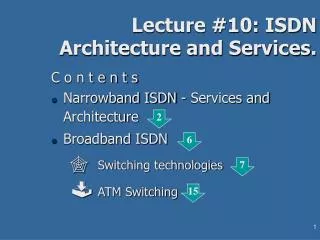
Lecture #10: ISDN Architecture and Services. C o n t e n t s Narrowband ISDN - Services and Architecture Broadband ISDN Switching technologies ATM Switching. 2. 6. 7. 15. ISDN Services.

Lecture #10: ISDN Architecture and Services.
E N D
Presentation Transcript
Lecture #10: ISDN Architecture and Services. C o n t e n t s • Narrowband ISDN - Services and Architecture • Broadband ISDN • Switching technologies • ATM Switching 2 6 7 15
ISDN Services • ISDN - Integrated Services Digital Network - communication technology intended to pack all existing and arising services: • digitized voice services (caller ID, messaging, persistent calls, redirected calls, multicast calls, waiting calls, in-call functions) • multimedia quality exchange • enhanced digital services - computer interconnection • entertainment services - TV, VOD (video on demand)
N-ISDN Architecture • Narrowband ISDN communications are based on bi-directional serial digital exchange (“bit pipe”) between end-user devices and the public service network; circuit switching technology • Digitized user devices: phone, fax, terminal (incl. VOD services) • Network congestion method: time division multiplexing over the bit stream according 2 standards: • low bandwidth: single channel for home use • high bandwidth: multiplied single channels for business use.
N-ISDN Architecture • Basic ISDN configuration • Low bandwidth • NT1 - Network Terminating device by the user’s place • passive bus connection between NT1 and user devices (up to 8 devices per connection) - ITU-T standard reference point “T” • twisted pair between NT1 and Carrier’s office (up to few km) - ITU-T standard reference point “T”. • Extended ISDN configuration • High bandwidth • NT1 • NT2 - small ISDN switch “PBX” (Private Branch Xchange) by the user’s office • passive connections between NT2 and user ISDN devices - ITU-T standard reference point “S” • optional terminal adapter TA supporting interface to one or more non-ISDN terminals - reference point “R”. 2/41a 2/41b
N-ISDN Performance • ITU-T standard allows • Basic bit pipe: 128kb/S voice/data channel + 16kb/S signaling • Primary bit pipe: combination up to 1.92Mb/s + 16-64 kb/S signaling (to fit in the ITU-T E1 PCM carrier of 2.048Mb/S) • Obsolete standard regarding audio/video communications (because of the low transfer rate) • Data applications: inapplicable by open system interconnections but still good for non-interactive and non-real-time applications (Internet, remote access to databases, etc.) 2/42
Broadband ISDN 155 Mb/S digital virtual circuit for fixed size data packets • enough rate for hard transfer applications like digital transmission of High Definition Television (HDTV) • ATM based technology • packet switching • high speed transmission media up to the customer device - basically fiber optics • New switching principles differing from multistage and time-division switches • Joint existence of PSTN, N-ISDN and B-ISDN.
Switching technologies • Switching technologies have been developed for end to end routing of the data flows. The following switching technologies are available today: • Circuit Switching which is based on the division of the transmission capacity into fixed timeslots called as channels or circuits. Channels are allocated end to end between users. • Packet Switching where variable length data units (from 40 to 4000 octets) are stored and forwarded in each network node. • Cell Switching where small fixed length data units called cells (ATM 53 octets) are stored and forwarded.
Circuit Switching • Circuit switching has been the first approach to routing communication channels between users. The originating user request the connection establishment with the user signaling. If the channel is available, it will be established between the communicating parties for the complete duration of the connection and remains occupied until either communicating end signals a disconnect request • Circuit switching has been used in classical POTS (Plain Old Telephone Service) and ISDN networks. Since the channel resource is occupied during the connection even if there is no traffic between the parties, the circuit switching with dedicated resources is considered more expensive than routing.
Packet Switching • Burst data traffic does not make efficient use of circuit switched transmission. Hence in 1960’s there was developed a new data communication approach called packet switching. • In packet switching variable length data units (from 40 to 4000 octets) are stored and forwarded in each network node. • Each packet contains additional information (in the packet header part) for routing, error correction, flow control etc. • Each packet is transferred to its destination independently. • In packet switching, network resources are used only when there is real information that is transferred.
Cell Switching • The newest switching technology calledCell Switchinguses small fixed length data units called cells (ATM 53 octets)thatare stored and forwarded. • Asynchronous transfer mode (ATM) is an example of a cell switched system. Its cell size is 53 bytes (header 5 + data 48 octets). • ATM is a compromise between the synchronous circuit-switched and the packet-switched systems both in delays, resource use and complexity. • Cell switching is a preferred technology for theBroadband ISDNbecause of the flexible data transfer rates.
B-ISDN Virtual Circuit • Circuit switching technology of PSTN is replaced by B-ISDN virtual circuit (VC). • 2 categories virtual circuit • Permanent virtual circuit - guarantied access and rate between several service access points (SAP) of the subscriber • Switched virtual circuit - non-guaranteed access and rate, they are granted after the request and last only during the service period
B-ISDN Virtual Circuit • Switching the virtual circuit does not mean commutation like by classical circuit switching but in fact routing, i.e. • virtual circuit switches are routers • virtual path (VP) is a collection of records in the router tables • like IP routing, the control information resides in the packet’s header but • unlike IP routing, the header contains virtual circuit ID instead of “source/destination” record 2/43
B-ISDN Virtual Circuit • Permanent VC have (for agreed period): • reserved records in the routing tables describing the route of the circuit • allocated weighted communication capacity (bandwidth and inside-switch buffers/lines) - not as monopoly wasteful allocation of the leased lines by the circuit switching • Switched VC have and dynamically for the period of communication i.e. there exists setup delay (for specifying records in routing tables and possibly for waiting free resources or allocating buffers) in the beginning of each communication process. Period charge Traffic charge
ATM Transmission 2/44 • Asynchronous transmission: • no ordering among the cells • no specified period between consecutive cells of a transmission • possibility for blank space between data cells - filling of service cells • Transmission media is [chiefly] fiber optic; therefore: • point-to-point network topology of 2 parallel unidirectional links between any two points in full-duplex transmission • each network point is either user-device or network switch • multicasting is done by propagation of cells in the switches: 1 cell to multiple outputs • standardized basic rate 155,52 Mb/S and extended rate 622.08 Mb/S (4 times) • In layered model the ATM physical layer consists of • Physical Media Dependent (PMD) sublayer specifies bit-stream parameters for different media - fiber, twisted pair • Transmission Convergence (TC) sublayer transfers the PMD bit-stream into ATM cells and present them to the ATM layer In contrast to the synchro-nous PCM carrier T1
ATM switching • Conceptually, switching is “the establishing, on demand, of an individual connection from a desired inlet to a desired outlet within a set of inlets and outlets for as long as is required for the transfer of information” (ITU-T). • In the case of ATM, this means that in an ATM network switching node (switch) ATM cells are transported from an incoming logical channel (VP/VC) to one or more (by multicasting) outgoing logical channels. • The establishment of logical channels is controlled by network management operations (specify VP interconnection) or directly by user or network signaling (specify VC interconnection). • A logical channel is identified by • the number of the physical link and • the identity of the channel (VPI/VCI) on the physical link
ATM Switch cell x, Ti Input stage 1 Output stage 1 cell x, Ti+1 N Incoming links carrying cells Input stage 2 Output stage 2 Cross connecting switch M Outgoing links carrying cels Because of the equal length of the cells (unlike the variable length of the packets) Input stage N Output stage M (! For bi-directional lines M = N) • Synchronously working in 3 cycles: fetching cells in some/all of the input lines, reorder the cells in cross-connecting switch and transmit the cells on appropriate output lines • For 150Mb/S VC and 53b/cell Ti+1-Ti2.7mS i.e. 360000 cells/S. • For 622Mb/S VC and 53b/cell Ti+1-Ti0.7mS i.e. 1380000 cells/S. • M, N may vary between 16 and 1K
ATM Switching • Rules: • Reduce cell loss rate (normally 10-12, but not 0) • FIFO discipline of cell service for each VC (virtual circuit) • Input queuing: 2 and more cells competing for the same output are stored in line in their input stages; only one of them is transmitted to the output (in random/Round-robin or other selection) Head-of-line-blocking effect: the newly arrived cells in the next cycle[s] wait because of rule - although their output is free • [Alternative to ] Output queuing: conflicting cells are stored in the output stage. No possibility for blocking; less delay for queued cell[s]; simpler circuit implementation 2/46 2/47
ATM Switches - Knockout • Applies crossbar switching and output buffering: • allows multiple input cells to reach the same output stage output buffering is needed • allows multi-/broad-casting: an input cell can reach multiple or all of output stages • The number of output buffers per stage is n < N (the incoming lines number); if the number of collisions for output ici > n then (ci-n) cells are discarded (“knocked out”) by special device - “concentrator” (cost-performance optimization of n) 2/48
ATM Switches - Banyan An East Indian fig tree (Ficus benghalensis) of the mulberry family which root form secondary trunks (NOT a banana tree!) • Applies multistage synchronous switchingin order to reduce switching elements number(for crossbars – N 2). • For 2:2 switching elements (typical) • the number of stages s = lbNand • the number of elements per stage e = N/2 • the number of switching elements S = se = 2-1N lbN(<< N 2) • Interstage communication pattern is such that: • there exists only one path from im to ok • at each stage the switching elements examine the consecutive bits of the destination address (1st stage-rightmost bit etc.) possible collisions on the outputs of the switching elements • Collisions are input-order-dependent; reordering the cells regarding to the output pattern solvethe collision 2/49 2/50a
ATM Switches - Batcher-banyan • Collision free extension of Banyan switches for the price of additional stages (i.e. hardware and delay) - a preceding switch reorders the cells of the input flow in a sorted order by the output indexes. • Applies multistage synchronous switching ; each switching element compares the whole destination field of the two input cells and switches them according to the stage pattern (arrow marks), that resembles the bubble sort • k input cells on N inputs are put in the first k outputs in sorted order • The interface between the Batcher and the Banyan switches is shuffle net 2/51