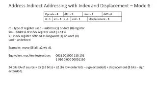
PIC18 Indirect Addressing
PIC18 Indirect Addressing. The PIC18 has three sets of INDF/FSR registers INDF0/FSR0, INDF1/FSR1,INDF2/FSR2. The INDFx registers work as on the PIC16; INDFx is used to access the value that FSRx is pointing to. movf INDF0, w ; w [FSR0]

PIC18 Indirect Addressing
E N D
Presentation Transcript
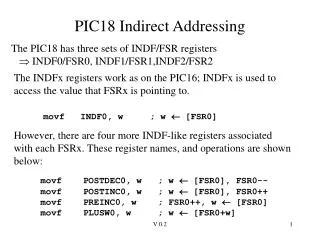
PIC18 Indirect Addressing The PIC18 has three sets of INDF/FSR registers INDF0/FSR0, INDF1/FSR1,INDF2/FSR2 The INDFx registers work as on the PIC16; INDFx is used to access the value that FSRx is pointing to.movf INDF0, w ; w [FSR0] However, there are four more INDF-like registers associated with each FSRx. These register names, and operations are shown below: movf POSTDEC0, w ; w [FSR0], FSR0-- movf POSTINC0, w ; w [FSR0], FSR0++ movf PREINC0, w ; FSR0++, w [FSR0] movf PLUSW0, w ; w [FSR0+w] V 0.2
Indirect Addressing Modes • The PIC18 advanced indirect addressing modes are common features on other processors. The features below are useful for stack data structures • postdec : post-decrement indirect addressing • postinc : post-increment indirect addressing • preinc : pre-increment indirect addressing • The plusw addressing mode is called indexed indirect. • This is a base addressing mode of every modern processor. • Allows an address to be computed by adding an offset to a base address. Very useful for array addressing (i.e., myarray[i]) V 0.2
The problem with Static Parameters An interruptis an external event to the processor (e.g. a change in pin voltage value) that causes the program to jump to an interrupt service routine (ISR). The ISR is finished, normal program execution is resumed. If the ISR calls Subr A, then static parameters are overwitten! Program Execution Interrupt occurs SubrA parameters main(), call Subr A interrupt service subroutine, callSubr Areturn from interrupt Used by main() call when interrupt happens. SubrA: .... .... return SubrA: .... ..... return ISR call to SubrA will change the parameters seen by main() call to SubrA V 0.2
/* variable left shift */ unsigned char vlshift(v,amt)unsigned char v, amt;{ while (amt) { v = v << 1; amt--; } return(v);} vlshift Revisited Data stack on entry to vlshift TOS+2: amt TOS+1: v FSR0 TOS: To pass these parameters, will use a data stack. This is a different stack from what is used for return addresses. This is just a data structure created by the programmer. v will be at FSR0+1 amt will be at FSR0+2 V 0.2
A data stack A data stack will be used to pass parameters. Will place the top-of-stack at location 0x7F, will want to the stack to grow down as items are placed on it. Will use FSR0 as the stack pointer stack growth 0x7f: ?? To store items on stack (push): movf POSTDEC0, w To access items on stack: static variables movf PLUSW0, w To remove items from stack (pop): 0x00: ?? movf PREINC0, w V 0.2
Use of data stack with vlshift() Before calling vlshift, main routine will push amt, v on stack. On entry to vlshift, stack will look like right. Data stack on entry to vlshift TOS+2: amt To perform “amt- - “ from within vlshift subroutine, will do: TOS+1: v FSR0 TOS: movlw 2 ; w = 2 decf PLUSW0 ; [FSR0+2]-- To perform “v = v << 1 “ from within vlshift subroutine, will do: bcf STATUS,C ; clear carry movlw 1 ; w = 1rlcf PLUSW0 ; [FSR0+1]-- V 0.2
vshift ;will use w to index to v movlw 2 movf PLUSW0,f ;test ‘amt’vshift_loop btfsc STATUS,Z ; amt==0? goto vl_return bcf STATUS,C movlw 1 rlcf PLUSW0 ; v = v << 1 movlw 2 decf PLUSW0,f ; amt-- goto vshift_loopvl_return ;; 'v' has result, pop off into w reg ;; before return movf PREINC0,w ; w <- v return vlshiftp18.asm(vlshift subr.) Want new v value to return in w reg, so pop this off of stack and place in w before returning. V 0.2
org 0 ;; initialize software stack ;; use FSR0 as software stack lfsr FSR0, 0x7f ; initialize main program variables movlw 0x24 movwf i ; i = 0x24 movlw 0x2 movwf j ; j = 2 ;; setup subroutine parms movf j,w movwf POSTDEC0 ; push amt value onto stack movf i,w movwf POSTDEC0 ;push v value onto stack call vshift movwf k ; k = vshift(v,amt); movf PREINC0,f ; pop amt off stack to clean up here goto here vlshiftp18.asm(main ) Place amt, then v onto data stack before call. The v parameter was removed from stack by vlshift; need to remove the amt parameter. V 0.2
Why use stacks for a parameter passing? Subroutine parameter variables are dynamically allocated. If subroutine is interrupted, then called again, this works because new space is allocated for parameters Program Execution Interrupt occurs Stack main(), call Subr A interrupt service subroutine, callSubr Areturn from interrupt SubrA parameters used by main() call SubrA: .... .... return SubrA: .... ..... return SubrA parameters used by interrupt service call V 0.2