HCS12 Technical Training Module
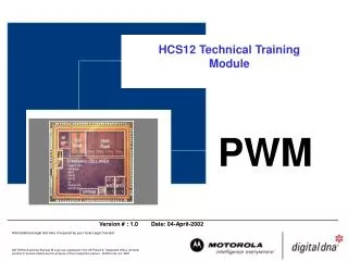
HCS12 Technical Training Module. PWM. 0 %. 10 %. 50 %. 90 %. Applications:. Digital-Analog Conversion Electrical Motor Control Tone Generation Sine Waveform Generation. 99 %. What is PWM?. T on. T off. Average. T period. 8-bit Counter. Clock. PWMCNTx.

HCS12 Technical Training Module
E N D
Presentation Transcript
0 % 10 % 50 % 90 % Applications: • Digital-Analog Conversion • Electrical Motor Control • Tone Generation • Sine Waveform Generation 99 % What is PWM? Ton Toff Average Tperiod
8-bit Counter Clock PWMCNTx Generation of PWM Signals (Edge Aligned) Start TPWM Reset 8-bit Compare = Period TPWM Pin PWMDTYx Duty Cycle TDuty PWMDTYx PWMPERx PWMPERx 8-bit Compare = PWMPERx 0x00 0x00 fClock, TClock
PWM Features 8 independent PWM channels with programmable period and duty cycle Four clock sources with programmable clock select logic Dedicated counter for each PWM channel PWM duty pulse polarity for each channel Enable/disable for each PWM channel Double Buffering of period and duty cycle Individual center aligned or left aligned outputs on each channel Resolution: 8-bit (8 channel), 16-bit (4 channel) Emergency shutdown with interrupt capability Operation Modes
Channel 0 Channel 7 Channel 6 Period and Duty Period and Duty Period and Duty Counter Counter Counter PWM Block Diagram Pin Pin ... Enable Pin Polarity Alignment Back
Four clock sources: Clock A (Ch 0, Ch 1, Ch 4, Ch 5) Clock SA (scaled A; Ch 0, Ch 1, Ch 4, Ch 5) Clock B (Ch 2, Ch 3, Ch 6, Ch 7) Clock SB (scaled B; Ch 2, Ch 3, Ch 6, Ch 7) Divide by Prescaler Taps: 2 4 8 16 32 64 128 PWM Clock Select (1 of 4) Clock A PWMSCLA @ $_08 Further Division of the clock: 2 4 6 8 ... 512 PWMPRCLK @ $_03 Clock SA Bus Clock PWMSCLB @ $_09 Further Division of the clock: 2 4 6 8 ... 512 Clock SB Clock B PRESCALE SCALE
= Unimplemented or Reserved PWM Clock Select - PRESCALE (2 of 4) PWMPRCLK @ $_03 Bit 0 Bit 6 Bit 5 Bit 4 Bit 3 Bit 2 Bit 1 Bit 0 R 0 PCKB2 PCKB1 PCKB0 0 PCKA2 PCKA1 PCKA0 W 0 0 0 0 0 0 0 0 Reset: Can be read and written anytime! x = A or B Software Examples Setting the PRESCALE Register: PWMPRCLK = 0x22; // B= Bus/4, A = Bus/4 PWMPRCLK = 0x07; // B = Bus, A = Bus/128
Example: Required: Clock Sx = 1 kHz Bus Clock = 16 MHz Prescaler = 128 Prescaler = 64 Clock x = 125 kHz Clock x = 250 kHz PWMSCLx = 63 PWMSCLx = 125 Clock Sx = 992 Hz Clock Sx = 1000 Hz Divide by Prescaler Taps: 2 4 8 16 32 64 128 PWM Clock Select - SCALE (3 of 4) PWMSCLB @ $_09 PWMSCLA @ $_08 Scale Value PWMSCLx PWMPRCLK @ $_03 Clock x 8-Bit Down Counter Bus Clock fBus Bit 7 Bit 6 Bit 5 Bit 4 Bit 3 Bit 2 Bit 1 Bit 0 Clock x = fBus / PWMPRCLK Count = 1 / 2 Clock Sx PWMSCLx = $00 PWMSCLx value is 256 Can be read and written anytime! x = A or B
PWM Clock Select (4 of 4) PWMCLK @ $_02 Bit 0 Bit 6 Bit 5 Bit 4 Bit 3 Bit 2 Bit 1 Bit 0 R PCLK7 PCLK6 PCLK5 PCLK4 PCLK3 PCLK2 PCLK1 PCLK0 W 0 0 0 0 0 0 0 0 Reset: PCLK7 — Pulse Width Channel 7 Clock Select 1 = Clock SB is the clock source for PWM channel 7. 0 = Clock B is the clock source for PWM channel 7. PCLK6 — Pulse Width Channel 6 Clock Select 1 = Clock SB is the clock source for PWM channel 6. 0 = Clock B is the clock source for PWM channel 6. PCLK5 — Pulse Width Channel 5 Clock Select 1 = Clock SA is the clock source for PWM channel 5. 0 = Clock A is the clock source for PWM channel 5. PCLK4 — Pulse Width Channel 4 Clock Select 1 = Clock SA is the clock source for PWM channel 4. 0 = Clock A is the clock source for PWM channel 4. PCLK3 — Pulse Width Channel 3 Clock Select 1 = Clock SB is the clock source for PWM channel 3. 0 = Clock B is the clock source for PWM channel 3. PCLK2 — Pulse Width Channel 2 Clock Select 1 = Clock SB is the clock source for PWM channel 2. 0 = Clock B is the clock source for PWM channel 2. PCLK1 — Pulse Width Channel 1 Clock Select 1 = Clock SA is the clock source for PWM channel 1. 0 = Clock A is the clock source for PWM channel 1. PCLK0 — Pulse Width Channel 0 Clock Select 1 = Clock SA is the clock source for PWM channel 0. 0 = Clock A is the clock source for PWM channel 0. Software Examples Select Clock Source: PCLK0 = 1; // SA is source of ch 0 PCLK6 = 0; // B is source of ch 6 PWMCLK = 0x11; // all channels Back
PWM Timer Channel PWMDTY0 @ $_1C PWMDTY1 @ $_1D PWMDTY2 @ $_1E PWMDTY3 @ $_1F PWMDTY4 @ $_20 PWMDTY5 @ $_21 PWMDTY6 @ $_22 PWMDTY7 @ $_23 Polarity Bit = 1 Duty = High Time Double Buffered 8-Bit Compare = PWMDTYx PWMDTYx Channel x x = 0 ... 7 8-Bit Counter PWMDTYx PWMCNTx PWMPERx PWMCNT0 @ $_0C PWMCNT1 @ $_0D PWMCNT2 @ $_0E PWMCNT3 @ $_0F PWMCNT4 @ $_10 PWMCNT5 @ $_11 PWMCNT6 @ $_12 PWMCNT7 @ $_13 PWMPER0 @ $_14 PWMPER1 @ $_15 PWMPER2 @ $_16 PWMPER3 @ $_17 PWMPER4 @ $_18 PWMPER5 @ $_19 PWMPER6 @ $_1A PWMPER7 @ $_1B 8-Bit Compare = PWMPERx PWMPERx Back Double Buffered
Enable/Disable PWM PWME @ $_00 Bit 0 Bit 6 Bit 5 Bit 4 Bit 3 Bit 2 Bit 1 Bit 0 R PWME7 PWME6 PWME5 PWME4 PWME3 PWME2 PWME1 PWME0 W Reset: 0 0 0 0 0 0 0 0 Channel 7 Channel 6 ... Channel 0 1 = Pulse Width channel x is enabled. The pulse modulated signal becomes available at PWM output bit x when its clock source begins its next cycle. 0 = Pulse Width channel x is disabled. Software Examples Enable/Disable PWM channels: PWME5 = 1; // Enable PWM channel 5 PWME3 = 0; // Disable PWM channel 3 PWME = 0xFF // Enable all 8 PWM channels PWME = 0; // Disable all 8 PWM channels Back
PWM Polarity Enable Register PWME @ $_00 Bit 0 Bit 6 Bit 5 Bit 4 Bit 3 Bit 2 Bit 1 Bit 0 R PPOL7 PPOL6 PPOL5 PPOL4 PPOL3 PPOL2 PPOL1 PPOL0 W 0 0 0 0 0 0 0 0 Reset: Channel 7 Channel 6 ... Channel 0 1 = PWM channel x output is high at the beginning of the period, then goes low when the duty count is reached. 0 = PWM channel x output is low at the beginning of the period, then goes high when the duty count is reached. PWMPERx PWMDTYx PPOLx = 1 PWMPERx Back PPOLx = 0 PWMDTYx
Left Aligned Output (1 of 3) Start Duty Cycle = 75 % Clock Source E = 100 ns Period = 400 ns Clock Source = E = 10 MHz (100 ns period) PPOLx = 0 PWMPERx = 4 PWMDTYx = 1 PWMx Frequency = 10 MHz/4 = 2.5 MHz PWMx Period = 400 ns PWMx Duty Cycle = ¾*100% = 75%
Center Aligned Output (2 of 3) Start Duty Cycle = 75% PWMDTYx E = 100ns PWMDTYx E = 100ns PWMPERx PWMPERx Period = PWMPERx*2 = 800 ns Clock Source = E = 10 MHz (100 ns period) PPOLx = 0 PWMPERx = 4 PWMDTYx = 1 PWMx Frequency = 10 MHz/8 = 1.25 MHz PWMx Period = 800 ns PWMx Duty Cycle = ¾*100% = 75%
PWM Center Align Enable Register (3 of 3) PWMCAE @ $_04 Bit 0 Bit 6 Bit 5 Bit 4 Bit 3 Bit 2 Bit 1 Bit 0 R CAE7 CAE6 CAE5 CAE4 CAE3 CAE2 CAE1 CAE0 W 0 0 0 0 0 0 0 0 Reset: Channel 7 Channel 6 ... Channel 0 CAEx – Center aligned Output Mode on channel x 1 = Channel x operates in Center Aligned Output Mode 0 = Channel x operates in Left Aligned Output Mode Back
16-Bit Resolution Two 8-bit channels of the PWM module can be concatenated to a 16-Bit PWM channel Clock Source 7 PWMCNT6 PWMCNT7 Period/Duty Compare PWM7 Back
Channel 0 Channel 6 Channel 5 Period and Duty Period and Duty Period and Duty Counter Counter Counter Emergency Shutdown Fault Input Emergency Shutdown Channel 7 PWMLVL=1 PWMLVL=0 PWM7INL=1 PWMLVL=0 ... PWMIE Interrupt PWMIF
= Unimplemented or Reserved PWM Shutdown Register PWMSDN @ $_24 Bit 0 Bit 6 Bit 5 Bit 4 Bit 3 Bit 2 Bit 1 Bit 0 R PWMIF PWMIE 0 PWMLVL 0 PWM7IN PWM7INL PWM7EN PWMR STRT W 0 0 0 0 0 0 0 0 Reset: Initialisation Set shutdown active level PWM7INL Set shutdown output level PWMLVL Interrupt Enable PWMIE Enable emergency shutdown PWM7ENA Back
Freeze Mode PFRZ = 0 1 PWM continue while in FREEZE Disable input clock to prescaler while in FREEZE Modes of Operation Wait Mode PSWAI = 0 1 Allow input clock to prescaler while in WAIT Stop input clock to prescaler while in WAIT
= Unimplemented or Reserved PWM Control Register PWMCTL @ $_05 Bit 0 Bit 6 Bit 5 Bit 4 Bit 3 Bit 2 Bit 1 Bit 0 R CON67 CON45 CON23 CON01 PSWAI PFRZ 0 0 W 0 0 0 0 0 0 0 0 Reset: 16 bit operation Enable/Disable clock In FREEZE Enable/Disable clock in WAIT Back
PWM Channel Period Registers PWMPERx @ $_14-_1B Bit 0 Bit 6 Bit 5 Bit 4 Bit 3 Bit 2 Bit 1 Bit 0 R Bit 7 Bit 6 Bit 5 Bit 4 Bit 3 Bit 2 Bit 1 Bit 0 W 1 1 1 1 1 1 1 1 Reset: Back
PWM Channel Duty Registers PWMDTYx @ $_1C-_23 Bit 0 Bit 6 Bit 5 Bit 4 Bit 3 Bit 2 Bit 1 Bit 0 R Bit 7 Bit 6 Bit 5 Bit 4 Bit 3 Bit 2 Bit 1 Bit 0 W 1 1 1 1 1 1 1 1 Reset: Back
Setup the PWM • Disable PWMPWME • Select clock (prescaler and scale) for the PWM PWMPRCLK, PWMSCLA, PWMSCLB, PWMCLK • Select polarityPWMPOL • Select center or left aligned modePWMCAE • Program duty cycle and periodPWMDTYx, PWMPERx • Enable used PWM channelsPWME