Download

1 / 66
720 likes | 1.04k Vues
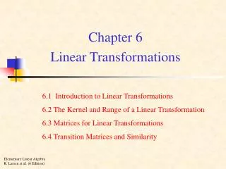
Introduction to RF Linear Accelerators Maurizio Vretenar – CERN BE/RF Divonne 2009.

E N D
Introduction to RF Linear Accelerators Maurizio Vretenar – CERN BE/RFDivonne 2009 • Why linear accelerators - basic concepts 2. Acceleration in Periodic Structures3. Overview of linac structures 4. Basics of linac beam dynamics 5. More on periodic structures 6. The Radio Frequency Quadrupole (RFQ) 7. Linac Technology 1
Why Linear Accelerators Linacs are mainly used for: • Low-Energy accelerators (injectors to synchrotrons or stand-alone) for protons and ions, linear accelerators are synchronous with the RF fields in the region where velocity increases with energy. As soon as velocity is ~constant, synchrotrons are more efficient (multiple crossings instead of single crossing). • Production of high-intensity proton beamsin comparison with synchrotrons, linacs can go to higher repetition rate, are less affected by resonances and have more distributed beam losses more suitable for high intensity beams. • High energy lepton colliders for electrons at high energy, main advantage is the absence of synchrotron radiation. 2
Proton and Electron Velocity b2=(v/c)2 as function of kinetic energy T for protons and electrons. electrons Classic (Newton) relation: Relativistic (Einstein) relation: protons “Newton” “Einstein” • Protons(rest energy 938.3 MeV): follow “Newton” mechanics up to some tens ofMeV (Dv/v < 1% for W < 15 MeV) then slowly become relativistic (“Einstein”). From the GeV range velocity is nearly constant (v~0.95c at 2 GeV) linacs can cope with the increasing particle velocity, synchrotrons cover the range where v nearly constant. • Electrons (rest energy 511 keV, 1/1836 of protons): relativistic from the keV range (v~0.1c at 2.5 keV) then increasing velocity up to the MeV range (v~0.95c at 1.1 MeV) v~c after few meters of acceleration in a linac (typical gradient 10 MeV/m). 3
Synchronism condition The distance between accelerating gaps is proportional to particle velocity Example: a linac superconducting 4-cell accelerating structure Synchronism condition bw. particle and wave t (travel between centers of cells) = T/2 d=distance between centres of consecutive cells • In an ion linac cell length has to increase (up to a factor 200 !) and the linac will be made of a sequence of different accelerating structures (changing cell length, frequency, operating mode, etc.) matched to the ion velocity. • For electron linacs, b =1, d =l/2 An electron linac will be made of an injector + a series of identical accelerating structures, with cells all the same length 4 Note that in the example above, we neglect the increase in particle velocity inside the cavity !
Linear and circular accelerators accelerating gaps d accelerating gap d d=bl/2=variable d=2pR=constant Linear accelerator: Particles accelerated by a sequence of gaps (all at the same RF phase). Distance between gaps increases proportionally to the particle velocity, to keep synchronicity. Used in the range where b increases. “Newton” machine Circular accelerator: Particles accelerated by one (or more) gaps at given positions in the ring. Distance between gaps is fixed. Synchronicity only for b~const, or varying (in a limited range!) the RF frequency. Used in the range where b is nearly constant. “Einstein” machine 5
Example 1: gap spacing in a Drift Tube Linac (low b) d Tank 2 and 3 of the new Linac4 at CERN: Beam energy from 10 to 50 MeV Beta from 0.145 to 0.31 Cell length from 12.3 cm to 26.4 cm (factor 2!) 6
Example 2: cavities in a superconducting linac (medium b) The same superconducting cavity design can be used for different proton velocities. The linac has different sections, each made of cavities with cell length matched to the average beta in that section. At “medium energy” (>150 MeV) we are not obliged to dimension every cell or every cavity for the particular particle beta at that position, and we can accept a slight “asynchronicity”. b=0.52 b=0.7 b=0.8 b=1 7 CERN (old) SPL design, SC linac 120 - 2200 MeV, 680 m length, 230 cavities
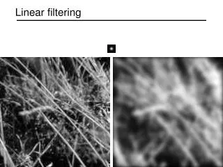
Wave propagation in a cylindrical pipe • In a cylindrical waveguide different modes can propagate (=Electromagnetic field distributions, transmitting power and/or information). The field is the superposition of waves reflected by the metallic walls of the pipe velocity and wavelength of the modes will be different from free space (c, l) • To accelerate particles, we need a mode with longitudinal E-field component on axis: a TM mode (Transverse Magnetic, Bz=0). The simplest is TM01. • We inject RF power at a frequency exciting the TM01 mode: sinusoidal E-field on axis, wavelength lp depending on frequency and on cylinder radius. Wave velocity (called “phase velocity”) is vph= lp/T = lpf = w/kzwith kz=2p/lp • The relation between frequencyw and propagation constantk is the DISPERSION RELATION (red curve on plot), a fundamental property of waveguides. RF input TM01 field configuration lp E-field B-field 9
Wave velocity: the dispersion relation The dispersion relation w(k) can be calculated from the theory of waveguides: w2 = k2c2 + wc2Plotting this curve (hyperbola), we see that: • There is a “cut-off frequency”, below which a wave will not propagate. It depends on dimensions (lc=2.61a for the cylindrical waveguide). • At each excitation frequency is associated a phase velocity, the velocity at which a certain phase travels in the waveguide. vp=∞ at k=0, w=wc and then decreases towards vp=c for k,w→∞. • To see at all times an accelerating E-field a particle traveling inside our cylinder has to travel at v = vph v > c !!! Are we violating relativity? No, energy (and information) travel at group velocity dw/dk, always between 0 and c. To use the waveguide to accelerate particles, we need a “trick” to slow down the wave. k=2p/lp vph=w/k = (c2+wc2/k2)1/2 vg=dw/dk 10
Slowing down waves: the disc- loaded waveguide Discs inside the cylindrical waveguide, spaced by a distance l , will induce multiple reflections between the discs. 11
Dispersion relation for the disc-loaded waveguide • Wavelengths with lp/2~ l will be most affected by the discs. On the contrary, for lp=0 and lp=∞ the wave does not see the discs the dispersion curve remains that of the empty cylinder. • At lp/2= l, the wave will be confined between the discs, and present 2 “polarizations” (mode A and B in the figure), 2 modes with same wavelength but different frequencies the dispersion curve splits into 2 branches, separated by a stop band. • In the disc-loaded waveguide, the lower branch of the dispersion curve is now “distorted” in such a way that we can find a range of frequencies with vph = c we can use it to accelerate a particle beam! • We have built a linac for v~c a TRAVELING WAVE (TW) ELECTRON LINAC mode B open waveguide dispersion curve mode A 12
Traveling wave linac structures beam • Disc-loaded waveguide designed for vph=c at a given frequency, equipped with an input and an output coupler. • RF power is introduced via the input coupler. Part of the power is dissipated in the structure, part is taken by the beam (beam loading) and the rest is absorbed in a matched load at the end of the structure. Usually, structure length is such that ~30% of power goes to the load. • The “traveling wave” structure is the standard linac for electrons from b~1. • Can not be used for protons at v<c: 1. constant cell length does not allow synchronism 2. structures are long, without space for transverse focusing 13
Standing wave linac structures To obtain an accelerating structure for protons we close our disc-loaded structure at both ends with metallic walls multiple reflections of the waves. Boundary condition at both ends is that electric field must be perpendicular to the cover Only some modes on the disc-loaded dispersion curve are allowed only some frequencies on the dispersion curve are permitted. In general: • the modes allowed will be equally spaced in k • The number of modes will be identical to the number of cells (N cells N modes) • k represents the phase difference between the field in adjacent cells. 14
More on standing wave structures • STANDING WAVE MODES are generated by the sum of 2 waves traveling in opposite directions, adding up in the different cells. • For acceleration, the particles must be in phase with the E-field on axis. We have already seen the p mode: synchronism condition for cell length l = bl/2. • Standing wave structures can be used for any b ( ions and electrons) and their cell length can increase, to follow the increase in b of the ions. Standing wave modes are named from the phase difference between adjacent cells: in the example above, mode 0, p/2, 2p/3, p. In standing wave structures, cell length can be matched to the particle velocity ! Synchronism conditions: 0-mode : l = bl p/2 mode: 2l = bl/2 p mode: l = bl/2 15
Acceleration on traveling and standing waves TRAVELING Wave STANDING Wave E-field position z position z 16
Practical standing wave structures From disc-loaded structure to a real cavity (Linac4 PIMS, Pi-Mode Structure) • To increase acceleration efficiency (=shunt impedance ZT2!) we need to concentrate electric field on axis (Z) and to shorten the gap (T) introduction of “noses” on the openings. • The smaller opening would not allow the wave to propagate introduction of “coupling slots” between cells. • The RF wave has to be coupled into the cavity from one point, usually in the center. 17
Comparing traveling and standing wave structures Standing wave Traveling wave Chain of coupled cells in SW mode. Coupling (bw. cells) by slots (or open). On-axis aperture reduced, higher E-field on axis and power efficiency. RF power from a coupling port, dissipated in the structure (ohmic loss on walls). Long pulses. Gradients 2-5 MeV/m Used for Ions and electrons, all energies Chain of coupled cells in TW mode Coupling bw. cells from on-axis aperture. RF power from input coupler at one end, dissipated in the structure and on a load. Short pulses, High frequency ( 3 GHz). Gradients 10-20 MeV/m Used for Electrons at v~c 18 Comparable RF efficiencies
3 – Examples of linac accelerating structures: a. protons, b. electrons, c. heavy ions 19
The Drift Tube Linac (also called “Alvarez”) Disc-loaded structures operating in 0-mode Add tubes for high shunt impedance Maximize coupling between cells remove completely the walls • 2 advantages of the 0-mode: • the fields are such that if we eliminate the walls between cells the fields are not affected, but we have less RF currents and higher shunt impedance. • The “drift tubes” can be long (~0.75 bl), the particles are inside the tubes when the electric field is decelerating, and we have space to introduce focusing elements (quadrupoles) inside the tubes. 20
More on the DTL Standing wave linac structure for protons and ions, b=0.1-0.5, f=20-400 MHz Chain of coupled cells, completely open (no walls), maximum coupling. Operating in 0-mode, cell length bl. Drift tubes are suspended by stems (no net current) Drift tubes contain focusing quadrupoles. E-field B-field 21
Examples of DTL Top; CERN Linac2 Drift Tube Linac accelerating tank 1 (200 MHz). The tank is 7m long (diameter 1m) and provides an energy gain of 10 MeV. Left: DTL prototype for CERN Linac4 (352 MHz). Focusing is provided by (small) quadrupoles inside drift tubes. Length of drift tubes (cell length) increases with proton velocity. 22
Example: the Linac4 DTL 352 MHz frequency Tank diameter 500mm 3 resonators (tanks) Length 19 m 120 Drift Tubes Energy 3 MeV to 50 MeV Beta 0.08 to 0.31 cell length (bl) 68mm to 264mm factor 3.9 increase in cell length beam 23
Multigap linac structures: the PI Mode Structure PIMS=PI Mode Structure Standing wave linac structure for protons, b > 0.4 Frequency 352 MHz Chain of coupled cells with coupling slots in walls. Operating in p-mode, cell length bl/2. beam 24
Sequence of PIMS cavities Cells have same length inside a cavity (7 cells) but increase from one cavity to the next. At high energy (>100 MeV) beta changes slowly and phase error (“phase slippage”) is small. 160 MeV, 155 cm Focusing quadrupoles between cavities 100 MeV, 128 cm PIMS range 25
Proton linac architecture – cell length, focusing period EXAMPLE: the Linac4 project at CERN. H-, 160 MeV energy, 352 MHz. A 3 MeV injector + 22 multi-cell standing wave accelerating structures of 3 types DTL: every cell is different, focusing quadrupoles in each drift tube CCDTL: sequences of 2 identical cells, quadrupoles every 3 cells PIMS: sequences of 7 identical cells, quadrupoles every 7 cells Two basic principles to remember: 1. As beta increases, phase error between cells of identical length becomes small we can have short sequences of identical cells (lower construction costs). 2. As beta increases, the distance between focusing elements can increase (more details in 2nd lecture!). Injector 26
Proton linac architecture – Shunt impedance A third basic principle: Every proton linac structure has a characteristic curve of shunt impedance (=acceleration efficiency) as function of energy, which depends on the mode of operation. The choice of the best accelerating structure for a certain energy range depends on shunt impedance, but also on beam dynamics and construction cost. 27
Multi-gap Superconducting linac structures (elliptical) Standing wave structures for particles at b>0.5-0.7, widely used for protons (SNS, etc.) and electrons (ILC, etc.) f=350-700 MHz (protons), f=350 MHz – 3 GHz (electrons) Chain of cells electrically coupled, large apertures (ZT2 not a concern). Operating in p-mode, cell length bl/2 Input coupler placed at one end. 28
Other superconducting structures for linacs Spoke (low beta) [FZJ, Orsay] CH (low/medium beta) [IAP-FU] QWR (low beta) [LNL, etc.] Re-entrant [LNL] HWR (low beta) [FZJ, LNL, Orsay] Superconducting linacs for low and medium beta ions are made of multi-gap (1 to 4) individual cavities, spaced by focusing elements. Advantages: can be individually phased linac can accept different ions Allow more space for focusing ideal for low b CW proton linacs 29
Quarter Wave Resonators Simple 2-gap cavities commonly used in their superconducting version (lead, niobium, sputtered niobium) for low beta protons or ion linacs, where ~CW operation is required. Synchronicity (distance bl/2 between the 2 gaps) is guaranteed only for one energy/velocity, while for easiness of construction a linac is composed by series of identical QWR’s reduction of energy gain for “off-energy” cavities, Transit Time Factor curves as below: “phase slippage” 30
H-mode structures Interdigital-H Structure Operates in TE110 mode Transverse E-field “deflected” by adding drift tubes Used for ions, b<0.3 CH Structure operates in TE210, used for protons at b<0.6 High ZT2 but more difficult beam dynamics (no space for quads in drift tubes) HSI – IH DTL , 36 MHz 31
Examples: an electron linac RF input RF output Focusing solenoids Accelerating structure (TW) The old CERN LIL (LEP Injector Linac) accelerating structures (3 GHz). The TW structure is surrounded by focusing solenoids, required for the positrons. 32
Examples: a TW accelerating structure A 3 GHz LIL accelerating structure used for CTF3. It is 4.5 meters long and provides an energy gain of 45 MeV. One can see 3 quadrupoles around the RF structure. 33
Electron linac architecture EXAMPLE: the CLIC Test facility (CTF) at CERN: drive linac, 3 GHz, 184 MeV. An injector + a sequence of 20 identical multi-cell traveling wave accelerating structures. Main beam accelerator: 8 identical accelerating structures at 30 GHz, 150-510 MeV 34
Examples: a heavy ion linac Particle source The REX heavy-ion post accelerators at CERN. It is made of 5 short standing wave accelerating structures at 100 MHz, spaced by focusing elements. Accelerating structures 35
Heavy Ion Linac Architecture EXAMPLE: the REX upgrade project at CERN-ISOLDE. Post-acceleration of radioactive ions with different A/q up to energy in the range 2-10 MeV. An injector (source, charge breeder, RFQ) + a sequence of short (few gaps) standing wave accelerating structures at frequency 101-202 MHz, normal conducting at low energy (Interdigital, IH) and superconducting (Quarter Wave Resonators) at high energy mix of NC-SC, different structures, different frequencies. 21.9 m 36
Longitudinal dynamics • Ions are accelerated around a (negative = linac definition) synchronous phase. • Particles around the synchronous one perform oscillations in the longitudinal phase space. • Frequency of small oscillations: • Tends to zero for relativistic particles g>>1. • Note phase damping of oscillations: At relativistic velocities phase oscillations stop, and the beam is compressed in phase around the initial phase. The crest of the wave can be used for acceleration. 38
Longitudinal dynamics - electrons • Electrons at v=c remain at the injection phase. • Electrons at v<c injected into a TW structure designed for v=c will move from injection phase j0 to an asymptotic phase j, which depends only on gradient and b0 at injection. • The beam can be injected with an offset in phase, to reach the crest of the wave at b=1 • Capture condition, relating E0 and b0 : Example: l=10cm, Win=150 keV and E0=8 MV/m. In high current linacs, a bunching and pre-acceleration sections up to 4-10 MeV prepares the injection in the TW structure (that occurs already on the crest) 39
Transverse dynamics - Space charge • Large numbers of particles per bunch ( ~1010 ). • Coulomb repulsion between particles (space charge) plays an important role. • But space charge forces ~ 1/g2 disappear at relativistic velocity Force on a particle inside a long bunch with density n(r) traveling at velocity v: B E 40
Transverse dynamics - RF defocusing • RF defocusing experienced by particles crossing a gap on a longitudinally stable phase. • In the rest frame of the particle, only electrostatic forces no stable points (maximum or minimum) radial defocusing. • Lorentz transformation and calculation of radial momentum impulse per period (from electric and magnetic field contribution in the laboratory frame): Bunch position at max E(t) • Transverse defocusing~ 1/g2 disappears at relativistic velocity (transverse magnetic force cancels the transverse RF electric force). • Important consequence: in an electron linac, transverse and longitudinal dynamics are decoupled ! 41
Transverse equilibrium in ion and electron linacs The equilibrium between external focusing force and internal defocusing forces defines the frequency of beam oscillations. Oscillations are characterized in terms of phase advance per focusing periodstor phase advance per unit lengthkt. Ph. advance = Ext. quad focusing - RF defocusing - space charge – Instabilities Approximate expression valid for: F0D0 lattice, smooth focusing approximation, space charge of a uniform 3D ellipsoidal bunch. Electron Linac: Ph. advance = Ext. focusing + RF defocusing + space charge + Instabilities For g>>1 (electron linac): RF defocusing and space charge disappear, phase advance →0. External focusing is required only to control the emittance and to stabilize the beam against instabilities (as wakefields and beam breakup). 42
Focusing periods Focusing provided by quadrupoles (but solenoids for low b !). Different distance between focusing elements (=1/2 length of a FODO focusing period) ! For the main linac accelerating structure (after injector): Protons, (high beam current and high space charge) require short distances: - blin the DTL, from ~70mm (3 MeV, 352 MHz) to ~250mm (40 MeV), - can be increased to 4-10bl at higher energy (>40 MeV). - longer focusing periods require special dynamics (example: the IH linac). Heavy ions (low current, no space charge): 2-10 bl in the main linac (>~150mm). Electrons (no space charge, no RF defocusing): up to several meters, depending on the required beam conditions. Focusing is mainly required to control the emittance. 43
High-intensity protons – the case of Linac4 Transverse (x) r.m.s. beam envelope along Linac4 Example: beam dynamics design for Linac4@CERN. High intensity protons (60 mA bunch current, duty cycle could go up to 5%), 3 - 160 MeV Beam dynamics design minimising emittance growth and halo development in order to: 1. avoid uncontrolled beam loss (activation of machine parts) 2. preserve small emittance (high luminosity in the following accelerators) 44
Linac4 Dynamics Prescriptions: 1. Keep zero current phase advance always below 90º, to avoid resonances 2. Keep longitudinal to transverse phase advance ratio 0.5-0.8, to avoid emittance exchange 3. Keep a smooth variation of transverse and longitudinal phase advance per meter. 4. Keep sufficient safety margin between beam radius and aperture Transverse r.m.s. emittance and phase advance along Linac4 (RFQ-DTL-CCDTL-PIMS) 45
Long chains of linac cells To reduce RF cost, linacs use high-power RF sources feeding a large number of coupled cells (DTL: 30-40 cells, other high-frequency structures can have >100 cells). Long linac structures operating in the 0 or p modes are extremely sensitive to mechanical errors: small machining errors in the cells can induce large differences in the accelerating field between cells. 47
Stability of long chains of coupled resonators Mechanical errors differences in frequency between cells to respect the new boundary conditions the electric field will be a linear combination of all modes, with weight (general case of small perturbation to an eigenmode system, the new solution is a linear combination of all the individual modes) The nearest modes have the highest effect, and when there are many modes on the dispersion curve (number of modes = number of cells !) the difference in E‑field between cells can be extremely high. 48
Stabilization of long chains: the p/2 mode Solution: Long chains of linac cells are operated in the p/2 mode, which is intrinsically insensitive to differences in the cell frequencies. Perturbing mode Perturbing mode Operating mode Contribution from adjacent modes proportional to with the sign !!! Contribution from equally spaced modes in the dispersion curve will cancel each other. 49
The Side Coupled Linac To operate efficiently in the p/2 mode, the cells that are not excited can be removed from the beam axis they become coupling cells, as for the Side Coupled Structure. multi-cell Standing Wave structure in p/2 mode frequency 800 - 3000 MHz for protons (b=0.5 - 1) Example: the Cell-Coupled Linac at SNS, >100 cells/module 50