The HIE-ISOLDE Faraday Cup
310 likes | 609 Vues
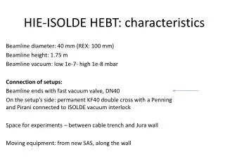
The HIE-ISOLDE Faraday Cup. BI Day December 6 , 2012 Alejandro Garcia Sosa W. Andreazza , E. Bravin , E. Daniel Cantero , M. Fraser, Y. Kadi , D. Lanaia , D. Voulot , F. Wenander. Contents. Introduction to HIE-ISOLDE The short diagnostic boxes Review of Faraday cups

The HIE-ISOLDE Faraday Cup
E N D
Presentation Transcript
The HIE-ISOLDE Faraday Cup BI Day December 6, 2012 Alejandro Garcia Sosa W. Andreazza, E. Bravin, E. Daniel Cantero, M. Fraser, Y. Kadi, D. Lanaia, D. Voulot, F. Wenander
Contents • Introduction to HIE-ISOLDE • The short diagnostic boxes • Review of Faraday cups • The HIE-ISOLDE Faraday cup • Simulations • Experimental Tests • Conclusions
1. Introduction to HIE-ISOLDE Intensity upgrade LINAC4+PSB Design Study of target area, Class-A lab and beam lines Energy upgrade 10 MeV/u Construction of SC LINAC + service buildings Beam quality upgrade RFQ cooler and buncher Solid state lasers for RILIS Higher mass resolving power HRS
1. Introduction to HIE-ISOLDE Intensity upgrade LINAC4+PSB Design Study of target area, Class-A lab and beam lines Energy upgrade 10 MeV/u Construction of SC LINAC + service buildings Beam quality upgrade RFQ cooler and buncher Solid state lasers for RILIS Higher mass resolving power HRS
1. Introduction to HIE-ISOLDE Intensity upgrade LINAC4+PSB Design Study of target area, Class-A lab and beam lines Energy upgrade 10 MeV/u Construction of SC LINAC + service buildings Beam quality upgrade RFQ cooler and buncher Solid state lasers for RILIS Higher mass resolving power HRS
2. The short diagnostic boxes Vacuum valves Class 100 ISO 5 Steerer magnet Short diagnostic box
2. The short diagnostic boxes • Currently being developed by CERN and Added Value Solutions (AVS) with the support of the Spanish government (CDTI) • The device fits in the 90 mm long space available and contains • A 45 degree scanning blade with 2 slits (H, V) • HIE-ISOLDE Faraday cup • Solid-state detector (Absolute energy, ToF) • Collimators blade • Attenuating and stripping foils
REX vs HIE - DBs • REX - Faraday cup (length: 59 mm) • MCP (beam profile - image) or Si detector (energy and TOF) • Collimators wheel (attenuating and stripping foils as well) • HIE -Faraday cup (14 mm) • Scanning slits (beam profile) • Collimators (optics) • Stripping foils in some cases • Solid-state detector in a few boxes (absolute energy, TOF) The most important device that needs to be tested is the FC
3. Review of Faraday cups • Destructive measurement • Measures absolute beam current • The escape of electronsincreases the value readin the picoammeter. • Ion-induced electron emission: • Low energy electrons (Ee < 20 eV) • High energy electrons (Ee~keV for MeV/u ions)
4. The HIE-ISOLDE Faraday cup HIE-ISOLDE REX-ISOLDE ISAC 2 59 14 30 26 (Distances in mm)
Electrons captured and retained Intensity:solid angle of the signal plate In a simplified model:W2 retained electronsW1 lost electrons Signal plate geometry
5. Simulations REX-ISOLDE Faraday cup potential distribution -60 V
5. Simulations REX-ISOLDE Faraday cup secondary e- tracking
5. Simulations • More uniform potential distribution • Enhanced effectiveness HIE-ISOLDE Faraday cup: -500V +100V
Definition of I0 stable beamA/Q =4 Vsignal plate = 0 V Vrepeller < 0 V (variable). SignalPlate Repeller
Biasing the repeller ring stable beamA/Q =4 Vsignal plate = 0 V Vrepeller < 0 V (variable). SignalPlate The short cup does not measure the same current value and needs much higher repelling voltage. Repeller ring Ground ring
Biasing the signal plate stable beamA/Q =4 Vsignal plate> 0 V (variable). Vrepeller= 0 V SignalPlate • High leakage current • Beam current does not reach a current plateau increasing the voltage Repeller ring Ground ring
Biasing repeller ring & signal plate stable beam A/Q =4 Vsignal plate > 0 V (variable) Vrepeller = -500 V SignalPlate Repeller ring Ground ring
7. Conclusions • Current measurements do not agree with the nominal beam current using the present design • Further improvements in the design are in progress • Beam profile measurements are unaffected in principle by a change in the design.
Acknowledgements • The ISOLDE Collaboration • The HIE-ISOLDE Project Team and groups within CERN Accelerator and Technology Sector • The Swedish Knut and Alice Wallenberg Foundation (KAW 2005-0121) • The Belgian Big Science program of the FWO (Research Foundation Flanders) and the Research Council K.U. Leuven • The CATHI Marie Curie Initial Training Network: EU-FP7-PEOPLE-2010-ITN Project number 264330. • The Spanish Programme “Industry for Science” from CDTI
Thank you! Work supportedbythe CATHI Marie Curie actionsundercontract GA-PITN-2010-264330.