Suspension service
Suspension service. Shock Absorbers and Ball Joints. Shock and strut diagnosis. The shock absorber/strut is the most commonly replaced component in the suspension system.

Suspension service
E N D
Presentation Transcript
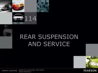
Suspension service Shock Absorbers and Ball Joints
Shock and strut diagnosis • The shock absorber/strut is the most commonly replaced component in the suspension system. • The shock absorber wears out slowly over time so it difficult to establish exactly when the shock/strut needs to be replaced.
Worn shock safety concerns • Besides ride quality a worn out or failed shock/strut can cause: • Reduced steerability – especially on rough roads • Increased braking distance
Shock/strut noise • Worn shock bushings and attachment hardware will produce a rattling noise when the vehicle is driven over uneven surfaces. • There are other suspension components that can cause a similar noise so a visual inspection is needed to identify the faulty part.
Visual inspection of shock/strut • Fluid leaking from the area around the seal indicates the seal has failed and immediate replacement is necessary. • A very small amount of fluid ‘mist’ around the seal is normal, but liquid coating the upper part of the shock is definite sign of seal failure. • Check for worn or broken rubber bushings.
Worn or damaged jounce stops • Split, cracked or damaged jounce stops are a sign of worn shocks and or springs. Jounce stop
Damaged dust bellows • Since the jounce stop is often integrated with the dust bellows a damaged, broken or torn dust bellows is a sign that the strut has lost dampening ability. Polyurethane jounce stop Is often molded as part of the bellows
Shock diagnosis • After a visual inspection of the shocks and suspension a road test is needed to assess the dampening ability of the shock. • Symptoms of worn shocks: • Excess pitch and roll oscillations after encountering bumps in the road. • Excessive dive during braking or squat during acceleration. • In general worn shocks produce a ride that is mushy and wallowing.
Strut mounts • Symptoms of worn or damaged strut mounts: • Rattling noise on uneven surfaces • Clunk noise when the vehicle is steered left and right • Notchy steering or frozen steering • Pull to either side • A worn or incorrectly installed strut mount will effect wheel alignment
Checking strut mounts Lateral freeplay • With the vehicle raised so that the tire is about 1 inch off the floor pry the tire upward to take some of the load off the mount. • Pry the center of the mount side to side to measure lateral freeplay. • Pry the whole strut up and down to measure axial freeplay Axial freeplay
Ball joint lubrication • Most modern passenger cars are built with sealed ball joints and tie rod ends that are greased for life and require no maintenance. • After market replacement ball joints often have grease fittings [Zerk fittings] that allow grease to be injected into the joint under high pressure.
Chassis lubrication • Heavy trucks normally have grease-able joints on all the suspension and driveline components. • Most automotive applications will use a general purpose GL-1 or GL-2 grease all of the suspension components with grease fittings.
NLGI grade number • Chassis grease standards are set by the National Lubricating Grease Institute • There a 9 grades ranging from 000 to 6 • The higher the number the thicker the grease.
NLGI grade number • Grease that is too thin will leak out of the joint. • Too thick and the grease cannot work its way in-between the ball and seat. • GL-1 and GL2 are the types of grease normally used in suspension and steering joints. • GL-2 has the consistency of peanut butter.
Zerk fitting • The only way to grease a ball joint is through a Zerk fitting. • The Zerk fitting couples the grease gun to the joint. • A spring loaded ball in the center of the fitting prevents grease from leaking out. • The Zerk fitting is screwed into the ball joint and can be easily replaced.
Grease guns • Most hand operated grease guns can produce 6000 psi or more. • Shops that work mostly on passenger cars will normally use hand operated grease guns as there are very few applications on modern cars that require periodic greasing. • Shops that work mostly on trucks will have pneumatically operated grease guns that save time when a vehicle has several dozen grease fittings.
Ball joint boots • Most modern passenger cars have sealed boots that a clamped tight to the ball joint with spring steel clips. • When greasing this type of joint you only pump one or two strokes of grease into the joint – untill the boot swells slightly.
Ball joint boots • Older cars and trucks may have loose fitting ‘umbrella’ type boots that allow a small amount of grease to leak out of the skirt. • Fill these ball joints until grease flows out of the boot skirt.
Ball Joints – visual inspection • A ball joint should last indefinitely if the rubber boot that retains the grease and keeps dirt and moisture out remains intact. • Any visible damage to the rubber boot is reason enough to replace the ball joint. • Grease-able ball joints will often have excess grease on the boot and control arm.
Checking ball joints for wear Gap between the rebound stop and upper control arm • If the spring is positioned on the lower control arm the upper and lower ball joints are under tension when the wheels are off the ground. • Place a jack stand under the lower control arm as far outboard as possible. • After lowering the vehicle on to the jack stand if there is a gap between the rebound stop and the upper control arm the ball joints are now unloaded. Frame
Checking ball joints for wear • If the spring is positioned on the upper arm the ball joints will be unloaded then the wheels are off the ground. • The rebound stop will be in firm contact with the upper arm. Rebound stop is in contact with the upper control arm Frame
Measuring ball joint freeplay • Freeplay measurements are made between the steering knuckle and ball joint/control arm in both axial and lateral directions. Dial indicator setup to measure lateral freeplay Lateral freeplay
Measuring ball joint freeplay • Specifications for ball joint freeplay can be found in AllData. Dial indicator setup to measure axial freeplay Axial freeplay
Replacing ball joints • Ball joints are retained in the control arms by: • Press fit [a snap ring may also be used] • Threaded • Rivets • Bolts • Integrated into the control arm [entire control must be replaced when ball joint is worn]
Press fit and threaded ball joint A special 8 point ball joint socket is needed to remove and install this type of ball joint
Ball joint retained by rivets • Replacing this type of joint requires that the rivets be drilled out. • Alternatively the heads of the rivets can be ground off using a die grinder. • Never cut the rivet heads off with an oxy-acetylene torch. • The new ball joint is retained with bolts and nylock nuts.
Integral and bolted ball joints • Ball joints that are retained by bolts are commonly found on vehicles with MacPherson struts. • Integral ball joints are bolded directly o the control arm. • The entire control arm is replaced when the ball joint is worn out.
Separating the ball stud • The ball stud is slightly tapered. • After the retaining nut has been removed several tons of force will be needed to separate the ball stud from the steering knuckle. Ball stud
Hammer method • This technique can only be used on forged steel steering knuckles. • Strike the steering knuckle on the area surrounding the ball joint tapered stud with the flat side of a 5 lbs, ball peen hammer. • Never strike the threaded part of the stud with a hammer.
Pickle fork method • Like the hammer method this technique should only be used on forged steel steering knuckles. • This technique will destroy the ball joint’s rubber boot so it is only used when replacing ball joints. • A similar forked tool can be used with a pneumatic hammer. Ball joint separator – AKA Pickle Fork
Screw type ball joint separator • The screw type separator does not damage the rubber boot or ball stud threads. • A steel disc positioned between the ball stud and the pushing screw distributes the force on the stud evenly. Steel disc protects the threads of the ball stud • Many technicians back of the retaining nut 3 or 4 turns but leave it on the ball stud to protect the threads of the stud.
Screw type ball joint separator • The are a number of screw type ball joint separators available to fit most applications. Images courtesy of OTC Corp.
Pinch bolt retained ball joints • Pinch bolts are often used to retain the ball joint stud to the steering knuckle. • A slot is cut through the steering knuckle into the ball stud hole. • A pinch bolt squeezes the steering knuckle tight to the ball stud, • The pinch bolt passes through a groove in the ball stud – insuring that the ball joint stays attached to the knuckle even if the bolt loosens. Groove for pinch bolt Pinch bolt
Ball joint press • A ‘C’-clamp type press is used to press the old ball joint out and press the new joint in while the control arm is still attached to the frame. Images courtesy of OTC Corp.
Pressing out ball joints • Press fit ball joints can be serviced on-the-car with a C-clamp type press or off-the-car using a hydraulic shop press. • A receiver sleeve is needed to support the control arm. • The receiver must be large enough to accept the large end of the ball joint. 1.875” 2.000”
Ball joint press Receiver • The receiver sleeve is often notched to allow clearance where sections of the control arm are very close to the ball joint bore. • A ram sleeve is needed to apply even pressure to the smaller end of the ball joint. Ram sleeve Adaptor collar Images courtesy of OTC Corp.
Ball joint press - removal • The inner diameter of the receiver must be slightly larger than the outer diameter of the ball joint. • The ram needs to be slightly smaller than the ball joint bore in the control arm. Receiver Control Arm Ram Collar • The press screw should be turned by hand. • Using an impact wrench damages the screw threads.
Ball joint press - installation • For installation we need to select a ram sleeve that fits the outer body of the ball joint. The ram sleeve must contact on this part of the ball joint Appling pressure to the softer metal parts closer to the center will damage the new ball joint Images courtesy of OTC Corp.
Ball joint press - installation • The receiver sleeve must be long enough to accept the full length of the ball stud. • The inside diameter of the receiver must slightly larger than the small end [un-flanged]of the ball joint. Ram sleeve Control Arm Receiver sleeve Collar
Castellated nut and cotter pin • The correct way to install the cotter pin on a castellated nut is shown on the left. • The excess on the lower side of the cotter pin is cut off with diagonal pliers before bending. Correct Incorrect
Ball joint R&R • If the ball joint is being replaced a hammer and pickle fork can be used.
Use a jack stand for safe removal • A jack stand is placed under the lower control arm to prevent possible injury when the steering knuckle is separated from the ball joint.
Pressing out the ball joint • Do not use an impact wrench with any type of screw press. Using an impact wrench damages the threads • A ½” ratchet with an 18” handle is the ideal tool for the job.
Control arm after removal • The hole in the control arm should be cleaned with sandpaper and lubricated prior to installing the new ball joint.
Installing the new ball joint • Insert the new ball joint in the control arm and place the receiver sleeve and adapter on top.
Install the pressing adapter • The adapter used to press the ball joint into the control arm needs to be sized so as to apply pressure to only the outer circumference of the ball joint.
Pressing in the new ball joint • Make sure the ball joint is aligned and straight as you press it into the control arm.
Check for gaps • Check to make sure there isn't any gap between the step on the ball joint and the control arm flange.