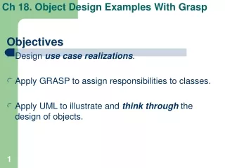
18. Object Design Examples with GRASP II
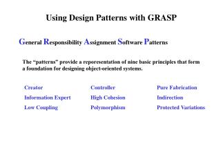
18. Object Design Examples with GRASP II. CSE 5324 Quiz 17 due at 5 PM, Thursday, 9 October 2014. 18.4 NextGen Use Case Realizations (etc.). Figure 18.13-18.19. Various sequence and design class diagrams. Review slides 5ff in the prior lecture… . How to Design makePayment :

18. Object Design Examples with GRASP II
E N D
Presentation Transcript
18. Object Design Examples with GRASP II CSE 5324 Quiz 17 due at 5 PM, Thursday, 9 October 2014
18.4 NextGen Use Case Realizations (etc.) Figure 18.13-18.19. Various sequence and design class diagrams. • Review slides 5ff in the prior lecture…. • How to Design makePayment: • The cashier enters the cash received from the customer. • We design the contract’s verbal post conditions, one at a time. • Creating the Payment: • The Expert pattern points out that Register initially has the the payment amount, and it is inspired by the real domain that records account information. But Sale uses Payment, so Expert also supports Sale’s creating Payment. • With two excellent choices, we closely examine cohesion and coupling. We rationalize that Sale is more closely coupled to Payment, and Register would be more cohesive with fewer jobs to do (Figure 18.13). • Logging a Sale: • The post conditions require that the store log its history of all sales, so the Expert pattern asks who is responsible for knowing and logging all sales? • Sale is getting overworked (incohesive), so perhaps a SalesLedger could offload this work (Figure 18.14). • But that would lead the OD designers to change an OA requirement. “What’s in a name—would a rose of any other name smell as sweet?” No, let the already required Store do the work of the proposed SalesLedger (Figure 18.15). • Calculating the Balance: • The Process Sale use case implies a need to display the customer’s account balance. • The Model-View Separation principle says the domain level design can’t display it, but must know it. • Payment knows about cash tendered, but only Sale knows all (Figure 18.16).
18.4 NextGen Use Case Realizations (etc.) Figure 18.13-18.20. Various sequence and design class diagrams. • The Emergent NextGenDCD for Iteration-1: • Having realized the requirements of the Process Sale use case, Figure 18.17 is Iteration-1’s emergent domain layer design class diagram (DCD). • The user interface (UI) and service layers have yet to be designed, however. • And the coders can be expected to do a little more (light) design work. • Connect the UI and Domain Layers (Figure 18.18): • The NextGen application’s Java main() method calls a Factory initializer object to create both the UI object and the domain object. • The new UI object gets a pointer to the Register domain object from the factory. • Now the UI object can forward every system event message (e.g., enterItem, endSale) through the Register façade controller to all domain level software. • To display a running total after every enterItemsystem event, the UI could: • Send getTotal to Register, which it would immediately delegate to Sale. • Ask Register for a pointer to Sale, so that the UI could get the total itself. The latter alternative is better, because it helps maintain Register’s cohesiveness. And its added UI-domain layer coupling is to the Sale object, which is unlikely to change. • Initialization and the ‘Start Up” Use Case: • Design the initialization last—after all need initialization activities have been discovered. • How to Start Up Applications: Declare a constructor in C++, or let Java main call its Factory. • Choosing the Initial Domain Object: Cohesion and coupling suggest Store (contains all other objects) is better than Register (the façade controller). • Store.create Design: Java main -> Store -> Register and ProductCatalog -> ProductDescription (Figure 18.20 Emergent UI layer design).
18.5 Monopoly Use Case Realizations Figure 18.21-18.27. Domain Model & various sequence and design class diagrams. • Two system operations: initialize and playGame. • PlayGame Design: Human observer presses the (one-and-only) “play game” button. • Controller Class: Choose MonopolyGame, the root object that contains most other domain objects, because only two system operations do not present a risk of becoming incohesive. • Game-Loop Algorithm: Monopoly use case (p.94) says pressing “play game” button simulates every player playing N times (N “rounds”). • Controlling Game Loop (Figure 18.23): • The Expert pattern assigns this “doing” responsibility to MonopolyGame, because it has information on current round count and all the players. • Inside a play-one-round loop is a small helper method with a single purpose (high cohesion). • Its playRound name is inspired by the Domain Model (low representation gap, LRG). • Object Takes Player’s Turn: The Expert assigns “taking a turn” to the Playerobject, not just for its LRG but because it knows more than any other object, except MonopolyGame, which is already heavily loaded. • Taking a Turn: • Requirement: Get random number, n, 2 < n < 12. • Design: By LRG, Die object returns value of faceValue attribute. • Requirement: Find new square location. • Design: By LRG, Board knows all of its squares. And by Expert, Board shall be responsible for rmeembering old square, accepting faceValue and returning new square. • Requirement: Move token there. • Design: By LRG, Player knows its Piece, and Piece knows its Square. By Expert, Piece will move itself, after getting Square from Player. • Coordinator: Player should coordinate the three steps above, because it is responsible for taking a turn. • Visibility: At initialization, Player must be given permanent references to Die, Board and Piece. • Emergent Design: Emerging static and dynamic design diagrams of PlayGameappear in Figure 18.25. • UML: The takeTurn message ref frame is informally expanded as an sd below it. The fvTot = maximum faceValue.= 12.
Monopoly Realizations (continued) • Command-Query Separation (CQS) Principle: • The roll method generates a random number that changes the state of Die, and the separate getFaceValue method returns the state of Die without changing its state. No method should do both. • Motivation: This adheres to the Principle of Least Surprise. A surprising example would be a getNewMissileName method, whose side effect is launching the named missile! • Initialize Design: • Choose MonopolyGame as root object, because it knows almost everybody. • The Creator pattern says it can create Board and Players, and Board can create Squares (Figure 18.27).
18.6 Iterative/Evolutionary OD Process • Model only the creative, difficult parts of the design. • Keep it light and short. • Move quickly to code and test. • Don’t try to detail everything in UML. • Design near the beginning of every iteration, for a short period before programming. • Work in a room full of hand-drawn diagrams and digital camera, occasionally using a tool that can translate UML into code and vice versa (Figure 18.28). • The OA software architect collaborates with designers. • Unified Process object design (Table 18.1): • Inception: Use cases. • Elaboration: Use case realizations partially designed for only the architecturally significant or risky scenarios. • Construction: Use case realizations for the remaining design problems.
18.7 Summary • Object design = capturing essential interactions and assigning responsibilities, guided by GRASP patterns and principles. • Choices affect: clarity, extensibility, maintainability, reusability, component quality.
R U O K ? Match the following design terms with their definitions below. • Use case realization (p.322). __ • Operation contract (p.326). __ • Domain Model (p.327). __ • Visibility (p.333). __ • Initial domain object (p.348). __ • Low representation gap (p.281). __ • Helper method (p.353). __ • Command Query Separation (CQS) Principle (p.358). __ • Principle of Least Surprise (p.358). __ • Object design (p.362). __ • A software design consisting of objects that collaborate in fulfilling stated requirements. • A rich source of easily understood object names, because of their low representation gaps (LRG). • A rich source of system operations and post condition state changes. • One object’s ability to reference another. • The first object(s) created at start up. • How we naturally think of a real-world domain concept and its straightforward correspondence with a software object. • A small method with a single purpose that supports high cohesion at the method level. • Don’t mix methods that change state with methods that return data to callers. • For example, don’t let a method that returns the number of available missiles actually launch one of them. • Capturing essential interactions and assigning responsibilities, guided by GRASP patterns and principles.
R U O K ? Match the following design guidelines with their definitions below. 11. Agile process (p.326). __ 18. Initial domain object (p.348). __ 12. Start Up (pp.328, 347). __ 19. Multiplicity (p.349). __ 13. Responsibilities (p.332). __ 20. Low representation gap (p.350). __ 14. Visibility (p.333). __ 21. Domain Model caveat (p.353). __ 15. Detail (p.337). __ 22. Competing partial information experts (p.354). __ 16. System operation message (pp.324, 338). __ 23. Future evolution (p.355). __ 17. Equally good choices (pp.341, 354). __ 24. UML ref and sd (p.357). __ • Control sequence diagram complexity by extracting pieces to a separate diagram. • When other guidelines don’t point at a clear responsibility winner, consider the next version’s cohesion and coupling problems. • To lower coupling, give the responsibility to the dominant one; i.e., the one with the mostinformation. • OO designs are not one-to-one simulations of how a real-world domain works, especially with respect to how people behave. • Look to the Domain Model for inspirations on naming software objects. • May not be the same in the Domain Model and the design. • A façade controller or an object that contains all or most other objects. • These motivate the designer to look closely at the alternatives’ cohesion and coupling implications. • A common way, but not the only way to start an interaction diagram. • Follow the same reasoning strategy in every Expert pattern application, and it will make even the difficult situations easier. • Necessary if an object is to send a message to another object. • Start designing them by clearly stating them. Then summarize the information that they require, and identify the classes that know it (p.336). • Design it last, after all initialization needs have been discovered. • Business people and developers must work together daily throughout project.