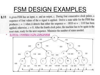
Design Examples
Design Examples. ELEC 418 Advanced Digital Systems Dr. Ron Hayne Images Courtesy of Thomson Engineering. BCD to 7-Segment Display. BCD to 7-Segment Display. entity BCD_Seven is port(BCD: in std_logic_vector(3 downto 0); Seven: out std_logic_vector(7 downto 1)); end BCD_Seven;


Design Examples
E N D
Presentation Transcript
Design Examples ELEC 418 Advanced Digital Systems Dr. Ron Hayne Images Courtesy of Thomson Engineering
BCD to 7-Segment Display 418_04
BCD to 7-Segment Display entity BCD_Seven is port(BCD: in std_logic_vector(3 downto 0); Seven: out std_logic_vector(7 downto 1)); end BCD_Seven; architecture Behave of BCD_Seven is begin process(BCD) begin 418_04
BCD to 7-Segment Display case BCD is when "0000" => Seven <= "0111111"; when "0001" => Seven <= "0000110"; when "0010" => Seven <= "1011011"; when "0011" => Seven <= "1001111"; when "0100" => Seven <= "1100110"; when "0101" => Seven <= "1101101"; when "0110" => Seven <= "1111101"; when "0111" => Seven <= "0000111"; when "1000" => Seven <= "1111111"; when "1001" => Seven <= "1101111"; when others => null; end case; end process; end Behave; 418_04
Synchronization & Debouncing 418_04
Single Pulser 418_04
Behavioral Model entity PULSE is port(SW, CLK: in std_logic; SP: out std_logic); end PULSE; architecture Behave of PULSE is signal Sync: std_logic_vector(2 downto 0) := "000"; begin process(CLK) begin if rising_edge(CLK) then Sync <= SW & Sync(2) & Sync(1); end if; end process; SP <= Sync(1) and not Sync(0); end Behave; 418_04
VHDL Test Bench entity Pulse_Test is end Pulse_Test; architecture Behave of Pulse_Test is component PULSE port(SW, CLK: in std_logic; SP: out std_logic); end component; signal SW, CLK: std_logic := '0'; signal SP: std_logic; constant CLK_period: time := 100 ns; begin uut: PULSE port map(SW, CLK, SP); 418_04
tb : process begin wait for 48 ns; SW <= '1'; wait for 1 ns; SW <= '0'; wait for 1 ns; SW <= '1'; wait for 1 ns; SW <= '0'; wait for 1 ns; SW <= '1'; wait for 1 ns; SW <= '0'; wait for 1 ns; SW <= '1'; wait for 1 ns; SW <= '0'; wait for 1 ns; SW <= '1'; wait for 1 ns; SW <= '0'; wait for 1 ns; SW <= '1'; wait for 1 ns; SW <= '0'; wait for 1 ns; SW <= '1'; wait for 485 ns; SW <= '0'; wait for 1 ns; SW <= '1'; wait for 1 ns; SW <= '0'; wait for 1 ns; SW <= '1'; wait for 1 ns; SW <= '0'; wait for 1 ns; SW <= '1'; wait for 1 ns; SW <= '0'; wait for 1 ns; SW <= '1'; wait for 1 ns; SW <= '0'; wait for 1 ns; SW <= '1'; wait for 1 ns; SW <= '0'; wait; end process; end; VHDL Test Bench 418_04
VHDL Simulation 418_04
VHDL Simulation 418_04
Adders • Ripple-Carry Adder • Concatenation of Full Adders • Carry Look-Ahead Adder • Fast Adder • Carry signals calculated in advance • Serial Adder • Single Full Adder • Shift and add one bit at a time 418_04
Ripple-Carry Adder 418_04
Carry Look-Ahead Adder 418_04
Generate (both 1) Propagate (either 1) Carry Look-Ahead (CLA) 418_04
4-bit CLA Adder • Limited by fan-in 418_04
16-bit CLA Adder 418_04
16-bit CLA Adder entity CLA16 is port(A, B: in std_logic_vector(15 downto 0); Ci: in std_logic; S: out std_logic_vector(15 downto 0); Co, PG, GG: out std_logic); end CLA16; 418_04
16-bit CLA Adder architecture Structure of CLA16 is component CLA4 port(A, B: in std_logic_vector(3 downto 0); Ci: in std_logic; S: out std_logic_vector(3 downto 0); Co, PG, GG: out std_logic); end component; component CLALogic is port(G, P: in std_logic_vector(3 downto 0); Ci: in std_logic; C: out std_logic_vector(3 downto 1); Co, PG, GG: out std_logic); end component; 418_04
16-bit CLA Adder signal G, P: std_logic_vector(3 downto 0); signal C: std_logic_vector(3 downto 1); begin CarryLogic: CLALogic port map(G, P, Ci, C, Co, PG, GG); ADD0: CLA4 port map(A(3 downto 0), B(3 downto 0), Ci, S(3 downto 0), open, P(0), G(0)); ADD1: CLA4 port map(A(7 downto 4), B(7 downto 4), C(1), S(7 downto 4), open, P(1), G(1)); ADD2: CLA4 port map(A(11 downto 8), B(11 downto 8), C(2), S(11 downto 8), open, P(2), G(2)); ADD3: CLA4 port map(A(15 downto 12), B(15 downto 12), C(3), S(15 downto 12), open, P(3), G(3)); end Structure; 418_04
Behavioral Model library IEEE; use IEEE.std_logic_1164.all; use IEEE.std_logic_unsigned.all; entity Adder_Behave16 is Port ( A : in std_logic_vector (15 downto 0); B : in std_logic_vector (15 downto 0); Ci : in std_logic; S : out std_logic_vector (15 downto 0); Co : out std_logic); end Adder_Behave16; 418_04
Behavioral Model architecture Behave of Adder_Behave16 is signal sum17: std_logic_vector(16 downto 0); begin sum17 <= ('0' & A) + (‘0’ & B) + (X”0000” & Ci); S <= sum17(15 downto 0); Co <= sum17(16); end Behave; 418_04
FPGA Synthesis Results 418_04
Serial Adder 418_04
Adder Comparison 418_04
Data Path and Controller 418_04
Add-and-Shift Multiplier • 4-bit Multiplicand • 4-bit Multiplier • 8-bit Product • 4-bit Adder • Controller 418_04
Add-and-Shift Multiplier 418_04
Multiplier Control 418_04
Behavioral Model library IEEE; use IEEE.std_logic_1164.all; use IEEE.std_logic_unsigned.all; entity Mult4X4 is port(Clk, St: in std_logic; Mplier, Mcand: in std_logic_vector(3 downto 0); Product: out std_logic_vector(7 downto 0); Done: out std_logic); end Mult4X4; 418_04
Behavioral Model architecture Behave of Mult4X4 is signal State: integer range 0 to 9; signal ACC: std_logic_vector(8 downto 0); alias M: std_logic is ACC(0); -- bit 0 of ACC begin process(Clk) begin if rising_edge(CLK) then case State is when 0=> if St='1' then -- Load ACC(8 downto 4) <= "00000"; ACC(3 downto 0) <= Mplier; State <= 1; end if; 418_04
Behavioral Model when 1 | 3 | 5 | 7 => if M = '1' then -- Add ACC(8 downto 4) <= '0' & ACC(7 downto 4) + Mcand; State <= State + 1; else -- Shift ACC <= '0' & ACC(8 downto 1); State <= State + 2; end if; 418_04
Behavioral Model when 2 | 4 | 6 | 8 => -- Shift ACC <= '0' & ACC(8 downto 1); State <= State + 1; when 9 => -- end of cycle State <= 0; end case; end if; end process; Done <= '1' when State = 9 else '0'; Product <= ACC(7 downto 0); end Behave; 418_04
VHDL Simulation 418_04
FPGA Implementation • Xilinx Spartan3e • 250K System Gates • 50 MHz Clock • ChipScope Pro • Virtual Input/Output Core (VIO) • Integrated Logic Analyzer (ILA) • Real-Time Verification • Captures On-chip Signals • Off-chip Analysis via JTAG Programming Cable 418_04
VHDL Test Bench entity testmult4x4 is port(CLK: in std_logic); end testmult4x4; architecture test1 of testmult4x4 is component mult4x4 port(Clk, St: in std_logic; Mplier, Mcand: in std_logic_vector(3 downto 0); Product: out std_logic_vector(7 downto 0); Done: out std_logic); end component; 418_04
VHDL Test Bench component ila port(control: in std_logic_vector(35 downto 0); clk: in std_logic; trig0: in std_logic_vector(17 downto 0)); end component; component vio port(control: in std_logic_vector(35 downto 0); clk: in std_logic; sync_in: in std_logic_vector(8 downto 0); sync_out: out std_logic_vector(8 downto 0)); end component; 418_04
VHDL Test Bench signal ... signal ... begin mult1: mult4x4 port map(CLK, St, Mplier, Mcand, Product, Done); i_ila: ila port map(control0, clk, trig0); i_vio: vio port map(control1, clk, sync_in, sync_out); 418_04
VHDL Test Bench trig0(17) <= st; trig0(16 downto 13) <= Mplier; trig0(12 downto 9) <= Mcand; trig0(8 downto 1) <= Product; trig0(0) <= Done; sync_in(8 downto 1) <= Product; sync_in(0) <= Done; St <= sync_out(8); Mplier <= sync_out(7 downto 4); Mcand <= sync_out(3 downto 0); end test1; 418_04
ChipScope Pro Analyzer 418_04
Array Multiplier 418_04
Array Multiplier 418_04
VHDL Simulation 418_04
Hardware Requirements • n-bit Multiplication (2n-bit Product) • n2 And Gates • (n-1) x n-bit Adders • 16-bit Multiplication • 256 And Gates • 15 x 16-bit Adders • 32-bit Multiplication • 1024 And Gates • 31 x 32-bit Adders 418_04
Signed Multiplication • Signed Binary Fractions • 2's Complement • S.XXX • ± . 1/21/41/8 • Four Cases • + + • + • + • 418_04
2's Complement Multiplier 418_04
Multiplier Control 418_04
Faster Multiplier 418_04
Multiplier Control 418_04
Behavioral Model -- This VHDL model explicitly defines control signals library IEEE; use IEEE.std_logic_1164.all; use IEEE.std_logic_unsigned.all; entity Mult2C is port(CLK, St: in std_logic; Mplier, Mcand: in std_logic_vector(3 downto 0); Product: out std_logic_vector (6 downto 0); Done: out std_logic); end Mult2C; 418_04