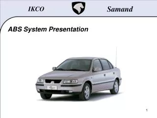
ABS System Presentation
IKCO. Samand. ABS System Presentation. Samand. Table of Contents. Introduction TEVES MK20 MANDO. Samand. Introduction… The Consequences Of Wheels Locking:. Longer stopping distance. Locking

ABS System Presentation
E N D
Presentation Transcript
IKCO Samand ABS System Presentation
Samand Table of Contents... • Introduction • TEVES MK20 • MANDO
Samand Introduction… The Consequences Of Wheels Locking: Longer stopping distance • Locking • Driver are familiar with the consequences of wheels locking, due to braking too hard for road surface adherence conditions: • The braking distance is longer, • There is no lateral guidance: • -The locked rear wheels often start to skid causing a spin, • -The locked front wheels lose their steer ability, the vehicle continues straight ahead. • There is abnormal tyre wear, • There is an increased risk of accident. • Even an experienced driver, in an extreme case, can lose control over the type and intensity of his braking. • Only an automatic control system can prevent the wheels from locking. But to anticipate locking, the system must be able to continually analyse the changes in the speed of each of the wheels, and to do so, it uses sensors. No lateral guidance ACCIDENT Tyre Wear
Samand TEVES MK20… 1. Operation Graph : • When the Vehicle is moving, the ABS ECU continuously monitors the Wheel Speed Data received from the Wheel Sensors and calculates the Reference Speed ( VREF ) • Based on the Reference Speed, the Wheel Slip Threshold ( ) can then be determined based on internal programmed maps • If, under braking situations, any of the vehicle wheel speeds drop below the Reference Speed (VREF), the ABS ECU will automatically control the braking pressure in the system via the ARU hydraulic block assembly.
Samand TEVES MK20… 2. Influence EBD system in ABS system:
Samand TEVES MK20… 3. ABS ECU and Additional Regulation Unit: 4 1 3 2 • ( 1 ) Re-injection pump. • ( 2 ) Hydraulic block. • ( 3 ) ABS ECU + solenoid valves. • ( 4 ) Pipes.
Samand TEVES MK20… 4. Location Of ABS ECU and Additional Regulation Unit:
Samand TEVES MK20… 5. Wheel Speed Sensors: • These are used to give the wheel speed information to the ABS electronic control unit (ECU), depending on which is fitted, in order to anticipate regulation in order to prevent the wheels from locking. • To acquire the wheel speeds, inductive sensors are used which measure the speed of each of the vehicle wheels on a toothed or magnetic pulse wheel.
Samand TEVES MK20… 6. Inductive Sensors: • Two-pole sensors have the advantage of delivering a stronger signal than a signal-pole sensor, and are less sensitive to out-of-round *. Furthermore, in order to obtain higher sensor sensitivity, the teeth on the pulse wheel must be such that a tooth is opposite one pole while the flat is opposite the other pole. A two-pole sensor can be compared to a sensor composed of two permanent magnets each of which has a winding. The aim is to filter spurious signals caused by pole gap vibration. • Out-of-round: pulse wheel axis off-centre in relation to the wheel axis witch causes variations in the gap over one rotation.
Samand TEVES MK20… 6. Inductive Sensors: • ( 1 ) Permanent magnet. • ( 2 ) Pole piece. • ( 3 ) Winding. • ( 4 ) Sensor body. • ( 5 ) Cogged wheel. • ( 6 ) Looped magnetic.
Samand TEVES MK20… 7. Inductive Sensors (front): • Radial reading.
Samand TEVES MK20… 7. Inductive Sensors (front): • Location of sensors.
Samand TEVES MK20… 7. Inductive Sensors (front): • Air gap: • 0.8 – 1.2 mm
Samand TEVES MK20… 8. Inductive Sensors (rear): • Axial reading.
Samand TEVES MK20… 8. Inductive Sensors (rear): • Location of sensors.
Samand TEVES MK20… 8. Inductive Sensors (rear): • Air gap • 0.8 – 1.2 mm
Samand TEVES MK20… 9. Testing the inductive sensors: • Measuring the signal with an oscilloscope at low speed: • The signal from these sensors may be tested by connecting an oscilloscope or AC voltmeter between its two conductors and turning the wheel. • To test the condition of the sensor, its resistance must be measured on its connector terminals.
Samand TEVES MK20… 9. Testing the inductive sensors: • Measuring the signal with an oscilloscope at high speed: • The signal amplitude and frequency increase in proportion to the wheel rotation speed.
Samand TEVES MK20… 10. Bleeding: • To diagnosis and bleeding should be use diagnosis tools.
Samand TEVES MK20… 11. Warning light: • In the event of a ABS function fault.
Samand TEVES MK20… 11. Warning light: • In the event of a Electronic Braking Distribution (EBD) fault
Samand MANDO… 1. Review of accommodation:
Samand MANDO… 2. ABS ECU and Additional Regulation Unit: 1 3 2 • ( 1 ) Re-injection pump. • ( 2 ) Hydraulic block. • ( 3 ) ABS ECU + solenoid valves.
Samand MANDO… 2. ABS ECU and Additional Regulation Unit: 4 3 7 8 1 10 2 5 9 6 • ( 1 ) Screw. • ( 2 ) Motor. • ( 3 ) Bearing. • ( 4 ) HCU block. • ( 5 ) Piston pump. • ( 6 ) LPA. • ( 7 ) Electrical valve. • ( 8 ) Electrical valve winding. • ( 9 ) ECU. • (10) Screw.
Samand MANDO… 3. Hall effect sensors operation: • ( A ) Magnetic target. • ( B ) Sensitive element. • ( C ) Permanent magnet. • ( D ) Integrated magnet sensor.
Samand MANDO… 3. Hall effect sensors operation: • A pulse is produced by passing magnetic target from in front of the sensors.
Samand MANDO… 3. Hall effect sensors operation: • When the resistance increases, the intensity decreases.
Samand MANDO… 3. Hall effect sensors operation: • When the resistance decreases, the intensity increases.
Samand MANDO… 3. Hall effect sensors operation: • Alternating magnetic poles hence alternating intensity.
Samand MANDO… 4. Internal diagram of the sensor:
Samand MANDO… 5. Hall effect sensors (front): • Radial reading. • Air gap: • 0.5 – 1.5 mm
Samand MANDO… 6. Hall effect sensors (rear): • Axial reading. • Air gap: • 0.5 – 1.5 mm
Samand MANDO… 7. Dynamic integrated magnet sensors (front): • Classic target.
IKCO Samand … The EndQuestions ?