Electromagnetics (ENGR 367)
350 likes | 534 Vues
Electromagnetics (ENGR 367). The Complete Sourced & Loaded T-line. T-line Power: Big or Small.

Electromagnetics (ENGR 367)
E N D
Presentation Transcript
Electromagnetics (ENGR 367) The Complete Sourced & Loaded T-line
T-line Power: Big or Small • While T-lines carry from the high voltage of Power Generators to the miniscule voltage detected by Communications Receivers, the load can only absorb as much signal power as is transmitted, and that depends initially on the source and input impedances. • To address this issue adequately, we must consider the fully sourced and loaded T-line.
Outline of Lecture • Model the Fully Sourced & Loaded T-line • Define Wave & Input Impedance of T-line • Form an Equivalent Circuit at the Input • Observe Special Input Impedance Cases • For a half-wavelength line • For a quarter-wavelength line • Work Out Examples of T-line Problems
Introduction: Practical T-lines Connect to Both Source and Load • Practical T-line may be mismatched at both ends • If fully unmatched, reflections occur at both ends
Sourced & Loaded T-line (lossless)(in case of lossy T-line, replace j with ) • Express the Phasor line Voltage & Currentas
Introduce Wave Impedance • Define Wave Impedance as the Ratio of Total Voltage to Current Anywhere on line • In terms of the voltage reflection coeff. ()
Wave Impedance & Input Impedance • In terms of line and load impedances • Define Input Impedance as the Wave Impedance at the front (source) end of line
Equivalent Circuit • The Practical Sourced & Loaded T-line with Zin • Acts like the equivalent circuit:
Special Case I • Half-Wavelength (/2) Line • Also known as the Half-Wave Transformer (HWT) • Electrical Length • Input Impedance • Notes on the HWT • Ideally, this T-line section is transparent to the source and acts as if it were absent from the circuit • Actually, any line loss results in less than ideal performance, so the shortest possible section is usually preferred in application • Results depend on frequency:
HWT Behavior • Due to the length of the HWT: • Provided:
Special Case II • Quarter-Wavelength (/4) Line • Also known as the Quarter-Wave Transformer (QWT) • Electrical Length • Input Impedance • Notes on the QWT • Ideally, can be used to match impedances at a junction • Affected by line losses so shortest section preferred • Results depend on frequency:
QWT Matching • Desire: • Provided:
Examples of T-line Problems • Consider a lossless 2-wire 300- line such as the lead-in wire from the antenna to a TV or FM radio communications receiver
T-line Problem: Example A • Given: ZG = Z0 = ZL = (Rin of Rx)= 300 vp = 2.5 x 10⁸ m/s and l = 2.0 m • Find: , SWR, , , , Zin, Vin, Iin, VL, IL, PL • Solution: line is matched at both ends!
T-line Problem: Example A • Solution: (continued)
T-line Problem: Example B • Given:a 2nd identical Rx in parallel with 1st so that ZG = Z0 = 300 ; ZL = Rin1 Rin2 • Find: , SWR, , , , Zin, Vin, Iin, VL, IL, PL with locations & values of Vmin, Vmax • Solution: ZL = (300 ) (300 )=150
T-line Problem: Example B • Solution: (continued) • Good News: Zin may be calculated or checked by MATLAB Zx on a lossless line to save complex arithmetic labor and show a graphical result!
T-line Problem: Example B • Solution: (continued)
T-line Problem: Example B • Solution: (continued) • Check with the graphical output of MATLAB Zx
T-line Problem: Example B • Solution: (note that for all real, resistive ZL & Z0) • The voltage min. occurs @ load if ZL<Z0 • The voltage max. occurs @ load if ZL>Z0 • For the phase of the voltage at the input versus the load
T-line Problem: Example C(based on Ex. 11.8, H&B, 7/e, p. 363) • Given: same T-line but add –j300 at load • Find: , VSWR, Zin, Iin, PL • Solution: now ZL = (150)(–j300)
T-line Problem: Example C • Solution: (continued)
T-line Problem: Example D(based on Ex. 11.9, H&B, 7/e, pp. 363, 364) • Given:same T-line as before but now use the purely capacitive load ZL = -j300 • Find: , VSWR, Zin Solution:
T-line Problem: Example E(based on D11.4&5, H&B, 7/e, p. 364) • Given: a 50- lossless line, l = 0.4 long, operating at 300 MHz with ZL = 40+j30 connected at z = 0, and a Thevenin Equiv. source of 12ej0 V at z = -l in series with ZTh= 50+j0 • Find: , VSWR, Zin, Vin, VL, PL • Solution:
T-line Problem: Example E • Solution: (continued)
T-line Problem: Example E • Solution: (continued)
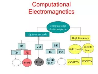
Methods of Solving T-line Problems • Analytical Expressions (as illustrated here) + No special tools needed other than calculator • Complex number calc’s may become tedious • Software Tools 1) MATLAB Zx for lossless lines (have access) 2) Other commercial programs for calc. & sim. • Graphical Tools: Smith Chart
Conclusions • Practical T-line problems must address both source and load conditions; if fully unmatched, reflections occur at both ends. • Input impedance (Zin) is the complex wave impedance at the source end of the T-line evaluated by analytical formula, MATLAB, other software tools or the Smith Chart.
Conclusions • The input impedance (Zin) reduces any sourced and loaded T-line to an equivalent circuit for the purpose of voltage, current and power analysis. • Certain T-line lengths (l) transform the load impedance (ZL) at the input in a special way • QWT: l =/4 Zin = Z02/ZL (good for matching) • HWT: l =/2 Zin = ZL (good for transparency)
Conclusions • To find average power delivered to the load (PL) of a sourced and loaded T-line • If one knows the • Thevenin equivalent source (Vth, Zth) • Characteristic Line & Load impedances (Z0,ZL) • T-line length, frequency & prop. velocity (l, f, vp) • then one can calculate • T-line electrical length ( = l) • Input impedance (Zin) • Power input (Pin) via equivalent circuit at the source and real power absorbed in the load
Conclusions • If the load is not matched to a T-line, some power reflects back to the source and may damage a generator if excessive • If the source is not matched to a T-line (not addressed in examples here!), power may reflect at both ends and calculations become more involved
References • Hayt & Buck, Engineering Electromagnetics, 7/e, McGraw Hill: New York, 2006. • Kraus & Fleisch, Electromagnetics with Applications, 5/e, McGraw Hill: New York, 1999.