Download
1 / 22
250 likes | 651 Vues
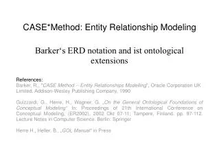
Barker‘s ERD notation and ist ontological extensions References: Barker, R., " CASE Method -- Entity Relationships Modelling ", Oracle Corporation UK Limited, Addison-Wesley Publishing Company, 1990

E N D
Barker‘s ERD notation and ist ontological extensions References: Barker, R., "CASE Method -- Entity Relationships Modelling", Oracle Corporation UK Limited, Addison-Wesley Publishing Company, 1990 Guizzardi, G., Herre, H., Wagner, G. „On the General Ontological Foundations of Conceptual Modeling“ In: Proceedings of 21th International Conference on Conceptual Modeling, (ER2002), 2002 Okt 07-11; Tampere, Finland. pp. 97-112. Lecture Notes in Computer Science. Berlin: Springer Herre H., Heller. B., „GOL Manual“ in Press CASE*Method: Entity Relationship Modeling
1. Introduction: conceptual modeling 2. Elements of Barker’s notation 3. Refinements of the model 4. Ontological extension Overview
Definition Conceptual modeling is an activity concerned with identifying, analyzing and describing the essential concepts and constraints of a domain with the help of a modeling language that is based on a small set of basic meta-concepts Guizzardi, Herre and Wagner The output of the conceptual modeling is a conceptual model (data model) No matter what is an adopted software life cycle model it is better not to skip conceptual modeling Introduction: conceptual modeling
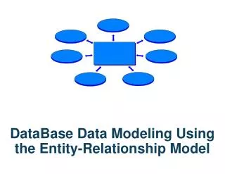
Data Modeling Techniques 1976, Entity Relationship modeling introduced by Peter Chan In the late 1980’s the introduction of "object oriented modeling" mid-1990's, the introduction of the UML Barker's Notation: originally developed by the British consulting company CACI promoted by Richard Barker adopted by the Oracle Corporation as a "CASE*Method" Barker's notation is supported by the CASE tool: Oracle Designer Business Process and Functions Data Flows Entity Relationships Introduction: data modeling techniques / Barker's notation
Basic Elements: Entity Attribute Relationship Unique identifiers Additional Constructs: Subsumption of entities Constraints on relationships Barker's notations: elements
An entity is a thing of significance,real or imagined, about which the information needs to be known. From an object oriented point of view an entity is a class From the perspective of relational db it is a relation Components: Name – singular form At least two attributes Notation: round cornered rectangle with a name, attributes and their types labels displayed inside it Entity PASSENGER # id * name * surname o phone
Attributes are aspects or properties that describe an entity Can be defined for existing entities only They can represent columns in a relation Components: unique name Type label Datatypes and domains are not included in the notation Attributes types: # Unique Identifier (UID), with # are marked attributes that constitute UID * Mandatory Attribute o Optional Attribute Attributes
All subtypes inherit the attributes of a supertype Exclusive subtypes – overlapping of subtypes is not allowed Presented as boxes inside the entity Subtypes of entities PERSON * name * surname PILOT * authorization PASSENGER o phone
Relationships are named significant associations between two entities Each relationship has: a name – proposition 2 endings Each relation ending has a name its optionality its cardinality Relationships
M:1 (Mandatory to Optional) M:1 (Optional to Optional) M:1 (Optional to Mandatory) M:1 (Mandatory to Mandatory) M:M (Optional to Optional) M:M (Mandatory to Optional) 1:1 (Mandatory to Optional) 1:1 (Optional to Optional) 1:1 (Mandatory to Mandatory) Relationships
Relationships PERSON * name * surname FLIGHT # flight no * status Involved in PILOT * authorization PASSENGER o phone Takes part in Each PILOT may be involved in one or many FLIGHTS In each FLIGHT must be involved exactly one PILOT One or many PASSENGERS can take part in one or many FLIGHTS In each FLIGHT must be involved one or many PASENGERS
Relationships Between two entities may be more than one relationship LOCATION * city * country FLIGHT # flight no * status start from to destination
UID is any combination of attributes and relationships which uniquely identifies an instance of an entity Attributes which are part of the UI are marked with # Relations are marked by a short line across the relationship near the entity being identified UID is a primary key Foreign keys are not displayed at the diagram Unique identifiers • AIRPLANE • # serial no • model • capacity uses performs FLIGHT # flight no * status
exclusive “or” is presented as an arc joining two relationships Constraints PERSON * name * surname FLIGHT # flight no * status PILOT * authorization in PASSENGER o phone Takes part in CARGO * substance * weight * capacity Transported in
Dealing with many-to-many relationships There are no means to implement in relational db many-to-many (M:M) relationship M:M relationships are omitted by the introduction of the intersection entity n-arity (where n>2) relations are introduced by means of the intersection entities too Refining the model FLIGHT # flight no * status PASSENGER # id * name * surname o phone PASinFLIGHT flight no pas id
Few distinct and intuitive symbols – easy to read for untrained users Optionality of attributes displayed Subtypes displayed inside an entity – unables modeling of deep hierarchical structures Relationships named by propositions not by verbs Constraints on relationships Comments
Identification of the model’s underlying upper-level ontology or ontologies. Annotation of the model elements to the elements of an underlying upper-level ontology. Constraint specification. Ontological refinement
Entity is something important in the modeled domain Everything can be an Entity For specifying what is an entity ontologies and specially upper-level ontologies can be used Ontological Concepts can be introduced to the model by means of ontological markers Analogously attributes and relationschips can be ontologically annotated Ontological refinements example: ontological markers FLIGHT <proc> # flight no * status
1. GOL category of process is assigned by marker <proc> to an entity FLIGHT. 2. Two following axioms of GOL are considered x (Proc (x) y ( Chron (y) prt(x,y)) (e1) x (Chron(x) ! y ! z (lb(x,y) rb(x,z)) (text) 3. Missing datas are found: Chron, prt, lb, rb; Ontological refinements example: ontological markers
4. Missing data may be added Ontological refinements example: ontological markers TIME <Chron> FLIGHT <proc> # flight no * status dep <lb> a) arr <rb> FLIGHT <proc> # flight no * status * time dep <lb> * time arr <rb> b)
validity checking, searching missing constraints providing well grounded foundations (formal semantics) for the models simplification of the modeling process Model integration based on underlying ontologies Ontological Refinement - Benefits
![Data Modeling [Comparison of data modeling techniques ]](https://cdn0.slideserve.com/205866/data-modeling-comparison-of-data-modeling-techniques-dt.jpg)