Download
1 / 248
2.5k likes | 2.67k Vues
Modeling Concepts and Overview of the Unified Modeling Language (UML). Modeling Introduction. What is a model? - Model is a representation or simplification of reality - Abstraction allows us to focus on the essential aspects of a model

E N D
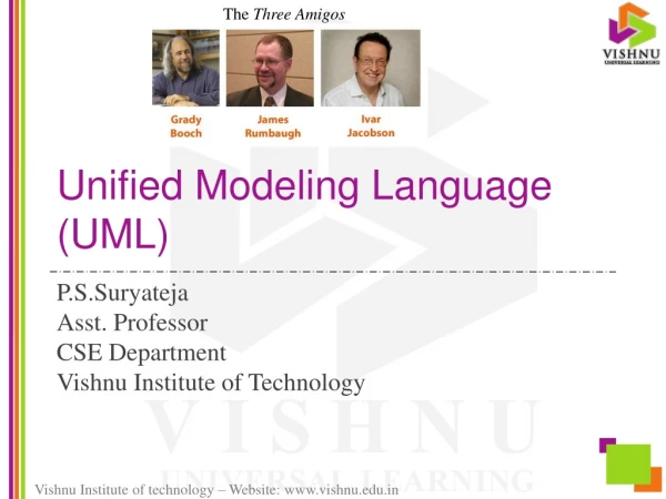
Modeling Concepts and Overview of the Unified Modeling Language (UML)
Modeling Introduction • What is a model? - Model is a representation or simplification of reality - Abstraction allows us to focus on the essential aspects of a model - A good model is the crux of good software development • Why model? - A good model helps us to visualize, specify, construct, and document what we are building - Models helps us to view (and understand) the system under development from different perspectives - Models obtained through abstraction enable us to handle complexity in a disciplined manner
Modeling Introduction contd..... - Models facilitate communication between the users, the developers, and other shareholders • Principles of Modeling - Choose the right model - Use different levels of abstraction - Models should be a reflection of reality - Different models, each representing different aspects (e.g., static vs dynamic features), are required to represent reality adequately
UML Overview What is the Unified Modeling Language (UML)? (Booch et al., 1999) • The UML is a modeling language (it has a vocabulary and rules for using the vocabulary) that allows us to visualize, specify, construct, and document the artifacts of a software system • For best results, the UML must be used in the context of a process that is use case driven, architecture-centric, iterative, and incremental • It is expressive, yet easy to use
Conceptual Model of the UML Conceptually, the UML consists of: • Building Blocks ( things, relationships, and diagrams) • Rules • Mechanisms
Things in the UML • Structural Things (interfaces, classes, use cases, collaborations, active classes, component, node) • Behavioral Things (interactions and state machines) • Grouping Things (packages) • Annotational Things (notes)
Relationships in the UML • Association • Generalization • Realization • Dependency
Diagrams in the UML • Use Case Diagram • Activity Diagram • Class Diagram • Object Diagram • Sequence Diagram • Collaboration Diagram • Statechart Diagram • Component Diagram • Deployment Diagram
UML Rules • A good (well-formed) model should conform to UML’s semantic rules • Semantic rules exist for names, scope, visibility, integrity, execution • Circumstances (such as the increasing complexity of a system under development) sometimes compel us to elide (hide details to simplify the view), leave out elements (incomplete model), or compromise the integrity of the model (inconsistent model)
Common Mechanisms in the UML • Specifications • Adornments • Common division ( class/object, interface/implementation) • Extensibility Mechanisms (Stereotypes, Tagged Values, Constraints)
Architecture • System should be viewed from a number of perspectives • Architecture deals with structural and behavioral aspects of a system, as well as with other concerns such as reuse, performance, scalability, functionality, constraints, trade-offs, and so forth • Five interlocking views may be used to delineate an architecture: Use Case View Design View (sometimes referred to as the Logical View) Process View Implementation View Deployment View
The Process • The UML should be used in the context of a process • For best results, the process should be: Use Case Driven Architecture-Centric Iterative and incremental • Typical phases of a process are: Inception - make a business case Elaboration - product vision & architecture, requirements, project plan, risk evaluation, basis for testing Construction - iteratively and incrementally build a product, test, refine designs, ensure consistency with requirements, acceptance criteria, etc., Transition - hand over the system to the end users, continually evaluate, improve, and enhance the system
OO Concepts • A class encapsulates data and procedures • A class is an abstraction that maps onto a real world abstraction • A class may be abstract or concrete
Example of a class public class Account { private String accountNumber; private float balance; public Account(String aNumber) { accountNumber = aNumber; } public void withdraw(float money) { ...... } public void deposit(float money) {.....} }
Object • An object is an instance of a class • It can be identified with some occurrence in the real world • Objects have identity, state, and behavior • Example: Account myAccount = new Account(“1000”); myAccount is an object
Instance Versus Class Variables • Instance variable: Each instance has its own value for that variable, e.g., each account instance has its own balance • Class variable: It is a variable that is shared by all instances of the class, e.g., A minimum balance for an Account may be shared by all Account instances
Inheritance • The properties of a superclass are acquired by the subclasses • The subclasses may override and/or extend the properties of the superclass • Example: In our example, Savings and Checking could be subclasses of Account
Polymorphism and Dynamic Binding • A client that deals with a class can also use the subclasses of that class • A polymorphic variable can refer to objects of different classes. Example: Account c = new Checking(); // c.withdraw(200.00); c = new Savings(); // c.withdraw(500.00); • A polymorphic function may take arguments of different types. Example: void f(Account anAccount) { .... } can be invoked with c as an argument as long c is an instance of Savings or Checking
Dynamic Binding • Binding that occurs at compile time is called Static Binding • Run time binding is referred to as Dynamic Binding • Dynamic binding gives run time flexibility
OO Analysis • OO Analysis: • Functional Requirements definition of the system • Description of classes in the problem domain • High-level system components and their interactions • Interaction between classes
OO Design • Transform analysis model into a feasible design • Define operations and other features • Define how these features are to be realized • Define organization of system in terms of building blocks
Why OO? • Flexibility - reuse, extensibility • OO development is a relatively seamless process • Abstractions/classes can be mapped onto real-world concepts • OO makes it easier to deal with complexity • Lends itself to prototyping
Different Views of a System • Functional View • Use cases provide a static functional view while activity diagrams give a dynamic functional view • Static Structural View • Class and object diagrams
Behavioral (Dynamic Structural) View • Interaction Diagrams • State Machines • Architectural View • Logical (e.g., Package Diagrams), hardware (e.g., Deployment Diagrams), process, and implementation (e.g., Component Diagram) architectures
What constitutes a flexible design? • High Cohesion • Classes should represent a single abstraction and each method should fulfill a responsibility • Low Coupling • Dependencies/interactions between classes should be minimized • Behavior should be evenly distributed • “Inquisitive’ control objects should be avoided • High modularity
System Functional Models • Functional model leads to design which in turn leads to implementation • Functional requirements define the requirements of a system from an external perspective
Types of Requirements • Functional - system does what is it supposed to do • Performance, e.g., response time • Robustness, e.g., exception handling • Compatibility with other systems, reusability, etc.,
Use Cases • Use cases represent the typical interactions between users and the system • A use case is a coherent unit of functionality that satisfies some user-visible function, thus helping the user achieve a discrete goal • Use cases could be trivial or non-trivial, big or small
Use Case Identification • Identify the actors • Determine the interactions between the actors and the system • What interactions are initiated by the actors? • What interactions are initiated by the system?
Use Case Identification • What information should the system store? How is this information created, stored, updated, deleted, and queried? • Are there any time-based activities performed by the system? • Are there any external events that affect the system? • Are there any activities performed when the internal state of the system changes?
Actors • Actors are external to the system • People (more specifically, roles of people), external systems that interface with the system being designed, and devices are typically the actors of a system • Actors may be primary or secondary (supporting) • Primary actors usually benefit from their interactions with the system
CATALOG ORDER SYSTEM PLACE ORDER CANCEL ORDER CANCEL ORDER ITEM CATALOG CUSTOMER RETURN ORDER ITEM
USES and EXTENDS relationships The behavior “Cancel Order Item” is always included in the “Cancel Order’ use case
<<extends>> Relationship <<extends>> The use case “Place Order’ sometimes includes the behavior of “Add Customer” (for example when “Place Order” attempts to create an order for a customer who has not yet been added to the system)
Use Case Specifications • A textual description of the use case should be made • The description specifies how the use case carries out its functionality • The description usually includes a trigger (what starts the use case?), pre-condition, flow of events, alternative flows, and post-conditions
Sample Use case Specification Name: Cancel Order Item Trigger: The use case starts when the telephone agent (for the customer) enters “Cancel Order Item” Pre-condition: An order o exists for the given order number Main flow of events: 1. Find all line items for the order o 2. For each line item found cancel line item end
Use case description continued... 3. Order is marked canceled and the use case ends Alternative paths If any of the line items is “Not pending”, the order cannot be canceled, and the use case ends Post-condition: The order has been marked canceled and saved
Activity Diagrams • Use case presents a static view of system functionality • The sequence of use case execution, conditions under which an extension occurs, and temporal relationships are hard to divine from use case diagrams • An activity diagram flowcharts the workflow of activities and presents the steps in a use case • An activity diagram is therefore a dynamic representation os system functionality
An activity in an activity diagram may be a task, another use case, or just a step being done in the use case End Start An activity A B Activity B follows A
Activity Diagram notations [x == 5] A B [x != 5] C You could also have nested decision points
Activity Diagrams notations B D A C Synchronization Bar
[COMMITTED] ENTER ORDER [DENIED] [APPROVED] SHIP ORDER AUTHORIZE FUNDS ALLOCATE INVENORY ACTIVITY DIAGRAM FOR PLACING AN ORDER