Download
1 / 21
210 likes | 375 Vues
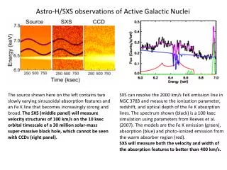
Astro-H XRT system. Contents 1. Astro-H satellite 2. XRT components & design 3. HXT (foil production, calibration facility) 4. SXT (improvements from Suzaku to Astro-H). H.Awaki (Ehime University) + Astro-H XRT team

E N D
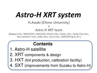
Astro-H XRT system Contents 1. Astro-H satellite 2. XRT components & design 3. HXT (foil production, calibration facility) 4. SXT (improvements from Suzaku to Astro-H) H.Awaki (Ehime University) + Astro-H XRT team (Nagoya Univ., NASA/GSFC, ISAS/JAXA, Ehime Univ., Chubu Univ., Osaka City Univ., Nara women’s Univ., Kobe Univ., Chuo Univ., JASRI/SPring-8, JST )
Astro-H The new Japanese X-ray mission following Suzaku Astro-H is currently planned to launch in fiscal 2013. Scientific objectives (1) Evolution of clusters of galaxies (2) Growth of super-massive black holes (3) Behavior of material in extreme gravitational field (4) Particle acceleration in the universe (5) Dark matter and dark energy Length: 14 m Weight: 2.5 t Launch vehicle: JAXA HII-A Orbit : 550 km circular i = 31 °
Instruments Hard X-ray telescope (HXT) Soft X-ray telescope Fixed Optical bench FL=12 m radiator FL=5.6 m Soft X-ray spectrometer Soft X-ray imager SUN (Micro calorimeter) (X-ray CCD camera) Extended Optical bench Soft Gamma-ray detector Hard X-ray Imager (HXI) Double-sided Si Strip (4 layer) detector + CdTe double strip(1 layer) detector Si/CdTe Compton camera With these instruments, Astro-H will cover the bandpass between 0.3 keV to 600 keV.
Main features of Astro-H • Large collecting area above 10 keV 200cm2 @ 40 keV • High-resolution spectroscopy with E/ΔE>1000 300cm2 @ 6 keV • Wide band observation from 0.3 to 600 keV. Effective area Energy resolution SXT+SXI Astro-H XMM-Newton HXT+HXI Collecting area in the soft X-ray band Effective area [cm2] 10 100 1000 Energy band SXT+SXS SGD (Compton mode) Chandra Suzaku Angular resolution 0.1 1 10 100 1000 Energy [keV] Collecting area in the hard X-ray band
Hard X-ray region: Continuum Sensitivity for point source Power law spectrum of a 1 mCrab source with Γ=1.7 ΔE/E=0.5 T=100 ks HXI simulation for absorbed AGNs (Terashima) 10-4 10-5 10-6 10-7 10-8 1 mCrab, NH=0 1 mCrab, NH=1024 cm-2 0.1 mCrab, NH=1024 cm-2 0.01 mCrab, NH=1024 cm-2 T=100ks Suzaku-HXD (PIN) Suzaku-HXD (GSO) Flux (photons s-1 keV-1 cm-2) ASTRO-H SGD 3% of NXB ASTRO-H HXI 1 10 100 5 10 20 50 100 200 500 Energy ( keV) Energy ( keV) Thank to the hard X-ray imaging system of Astro-H, the sensitivity for point sources is much improved above 10 keV. ⇒ The detection limit of Astro-H is about two orders of magnitude fainter than that of Suzaku PIN. We will be able to obtain a spectrum of 0.01 mCrab source with NH=1024 cm-2,
Main features of Astro-H • Large collecting area above 10 keV • High-resolution spectroscopy with E/ΔE>1000 • Wide band observation from 0.3 to 600 keV. Effective area Energy resolution SXT+SXI Astro-H XMM-Newton HXT+HXI Collecting area in the soft X-ray band Effective area [cm2] 10 100 1000 Energy band SXT+SXS SGD (Compton mode) Chandra Suzaku Angular resolution 0.1 1 10 100 1000 Energy [keV] Collecting area in the hard X-ray band
High resolution Spectroscopy in the soft X-ray region Mn Kα Astro-H/SXS FWHM ~4 eV • 5880 5900 5920 • Energy (eV) Takahashi et al. 2008, SPIE 1 10 Energy (keV) A large effective area with a high energy resolution is realized by the NASA/GSFC thin foil optics (SXT-S). The thin foil optics has benefits of light weight and high throughput.
Main features of Astro-H • Large collecting area above 10 keV 200cm2@40 keV • High-resolution spectroscopy with E/ΔE>1000 300cm2@6keV • Wide band observation from 0.3 to 600 keV. Effective area SXT+SXI We can obtain these features with X-ray telescope. HXT+HXI Effective area [cm2] 10 100 1000 SXT+SXS SGD (Compton mode) Telescope is crucial for Astro-H XRT system. 0.1 1 10 100 1000 Energy [keV]
2. XRT component TS is placed over the entire aperture of each mirror in order to isolate the XRT from space thermally. PC is set on the top on the mirror in order to reduce the stray light. Mirrors employ tightly-nested, conically approximated thin-foil Wolter-I optics. Without PC With PC Focal plane images formed by stray light These panels show simulated images of a point source locating at (-20’, 0) in cases of without and with pre-collimator . (Serlemitsos et al. 2007)
XRT design parameters - S PET 0.2 um Polyimide Light weight and high throuput t0.15, 0.23, 0.31 mm h100mmx2 ~210 ~1680 Weight ~56 kg ~ 80 kg Angular resolution 1 arcmin 1.7 arcmin
Hard X-ray Telescope (HXT) Depth-graded multilayer (ML) technology (supper mirror) 30 keV Supper mirror dn < d1 measurement model Pt/C Multilayer Critical angle of Pt at 30 keV (0.161 deg) Epoxy 0.02mm Al Substrate 0.2 mm Reflectivity of Super mirror coating on float glass. The periodic structure is 46-126 Å level and micro-roughness~3Å. Reflector of HXT with depth-graded ML is produced through a replication method The ML uses the Bragg reflection and enhance reflectivity beyond the critical energy by the X-ray interference.
Sputtering Chambers Sputtering Chamber
Foil Production @ Nagoya Univ. (1) Forming foil (2) ML coating (3) Spray epoxy (4) Curing (5) Separation (6) Finished reflector Quality check
Surface profile of the reflector Axial figure profile of a recently fabricated test reflector 2mm Replication mandrel (glass tube) Replicated reflector Reflectivity measurement E=30 keV σ~3A Figure error of this test reflector is ±1 micron (P-V). Based on a reflectivity measurement, surface roughness is about 3-4A, which is comparable to that of glass tube. smooth surface is trasferred to the foil.
Synchrotron radiation facility SPring-8 Super Photon ring 8GeV Synchrotron radiation ranging from the soft X-ray (E=300eV) to hard X-ray (E=300keV) region is available with high intensity. We use this facility for • Reflectivity measurement of an X-ray reflector • Image quality measurement of an XRT SPring-8 BL20B2 These data are valuable for making the response function of HXT.
Reflectivity measurement @ SPring-8 BL20B2 Experimental Hutch 2 & 3 beam size = 0.5x0.5mm E/DE~104 60 keV 30 keV measurement model measurement model
Image measurement @ SPring-8 BL20B2 Beam divergence < 1”, when beam size = 0.3x0.3mm Telescope holder HXT E/DE~104 Stages 12 m Direct beam after 4-axis slit XRT for a balloon bone experiment Telescope holder SUMIT XRT: 1.54 arcmin (HPD) (87pairs) Stages An X-ray image will be obtained by a pencil beam scan.
Soft X-ray telescope for SXS~improvements from Suzaku to Astro-H ~ • (1) Substrate Shaping • To use thicker Al substrate for the larger radii. • To use significantly larger number of forming mandrels for better substrate shaping • (2) Precise positioning • To make precise alignment bars • Reflector will be fixed onto the bar by glue • (3) Stronger housing • More mass is allocated to the mirror housing
Reflector fixing (testing with the Suzaku spare) 60 pairs Test 1.26 arcmin Suzaku (1.7arcmin HPD) Encircled Energy Function 0 0.5 1 ASCA (3.7arcmin HPD) 0 2 4 6 8 10 Diameter (arcmin) Okajima et al. 2009 Since groove width of alignment bar is wider than the reflector thickness by 25 µm and the reflectors are free to move. Test gluing using “the Suzaku spare hardware” ⇒ 1.26 arcmin (HPD) with 60 pairs. The reflector will be fixed onto the bar by glue for ASTRO-H in order to improve angular resolution.
Production schedule Mass production of HXT foils We will start mass-production of foils for HXT in April 2010. launch
Summary • Astro-H mission The new Japanese X-ray mission is currently planed to launch in 2013. the unique features are (1) Large collecting area above 10 keV (2) High-resolution spectroscopy with E/ΔE>1000 (3) Wide band observation from 0.3 to 600 keV. . • XRT system X-ray telescope system consists of two HXT (5-80 keV) and two SXT (0.3-10 keV). Mirrors employ tightly-nested, conically approximated thin-foil Wolter-I optics. HXTs employ Pt/C depth-graded multilayers, while SXTs employ a single layer of gold. • Current status We are performing test productions, and are tuning production facility. Based on basic studies, detailed studies of the flight design are in progress, and production facilities for the Astro-H XRT system are close to finish.