Download
1 / 104
1.04k likes | 1.34k Vues
Past, present and future of Gravitational Wave detection Science. J. Alberto Lobo, Bellaterra, 13-O ct o be r -2004. Presentation summary. Current GW detection research status: Acoustic detectors Interferometers LISA LPF and the LTP The Diagnostics and DMU subsystems

E N D
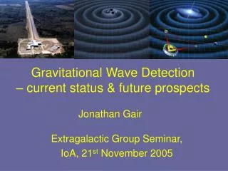
Past, present and future of Gravitational Wavedetection Science J. Alberto Lobo, Bellaterra, 13-October-2004
Presentation summary • Current GW detection research status: • Acoustic detectors • Interferometers • LISA • LPF and the LTP • The Diagnostics and DMU subsystems • Future prospects
There are two detection concepts at present Acoustic detection: Based on resonant amplification of GW induced tidaleffects. EXPLORER, NAUTILUS, AURIGA, ALLEGRO, NIOBE Interferometric detection: Based on GW induced phase shifts on e.m. waves. VIRGO, LIGO,GEO-600, TAMA Earth based GW detectors
Bar concept Idea of an acoustic detector (bar) is to link masses with a spring: so that and GW signal gets selectively amplified around frequencyW. Strong directionality
J. Weber Real bar detectors • Two well separated aluminum bars (~1000 km) • Resonance at ~1 kHz • Piezoelectric non-resonant transducers • Impulse sensitivity: • h~10-16 • Coincidence analysis • Tens of sightings claimed in one year • Claims questioned and eventually disproved • Hawking and Gibbons: energy innovation theory • Giffard: bar quantum limit New generation cryogenic and ultra-cryogenic bars
NAUTILUS, Frascati Dilution refrigerator: 50 mK Resonant transducer h ~ 5x10-19
Principle: Resonant energy transfer to & fro Mecahnical amplification Resonant motion sensor Beat spectrum:
NAUTILUS, 1999 Maximum bandwidth: Bar detector sensitivity
IGEC(International Gravitational Event Collaboration) • Essential results: • No impulse signals above 4x10-18 • Negligible false alarm when n>3 (<1/104 years) Various controversial, single detector claims available… Remarkable… but insufficient
Resonance condition: Interferometric detector working principle
Interferometric detector design Delay lines Fabry-Pérot arms: Photodiode: dark fringe: • Photon flux waste • Shot noise important Light recycling technique: • Power recycling • Signal recycling
Details of VIRGO Cascina site, near Pisa
Highly reflecting mirror Vacuum pipe Details of VIRGO
Summary status of LIGO Nov. 1999: Official inauguration Feb. 2002: Engineering run E7, 6 months Sep. 2002: Science run S1, 17 days, + TAMA + GEO-600 Feb. 2003: Science run S2, 59 days, Nov. 2003: Science run S3, 70 days, + TAMA + GEO-600 End of 2004: Science run S4: ~4 weeks Spring 2005: Commissioning, ~6 months Autumn 2005: Science run S5, ~6 months After: Full observatory operation
If… but… then… there are many GW sources at low frequencies Earth-based detectors are seismic noise limited the solution is to go out to space
1993. Europe/US team submits LISA proposal as M3 project of ESA’s Horizon-2000 Science Programme. LISA is changed to cornerstone mission in ESA’s Horizon-2000 Plus, and approved as ESA alone. 1994. • New studies to reduce cost: LISA is redefined as a three S/C Constellation, 1.4 ton payload. 1997. • NASA joins in (50% + 50%), launch advanced to ~2010. ESA’s FPAG recommends industrial study phase. 1998. System & Technology Study begins. Prime is Dornier Satellitensysteme, LIST strongly involved. 1999. Final Report delivered to ESA. 2000. TRIP Review panel considers LISAmedium risk. 2003. ESA’s 4th Nov SPC approves LISA, and LPF. 2003. NASA’s new exploration programme defers LISA to 2013. 2004. Brief chronology:
LISA concept Test masses 5 million km, 30 mHz Transponder scheme
Cumulative Weekly S/N Ratios during Last Year Before MBH-MBH Coalescence
inclination 0.01 eccentricity o 1 Orbit dynamics
The three spacecraft Science module Thermal shield Downlink antennas Solar panels Support structures FEEP Baffle Star tracker
Objective: Detection of GWs, sensitivity: 4x10-21 at 1 mHz Payload: Six test masses of Au-Pt alloy, 40 mm a side, in three S/C Six capacitive inertial sensors Six set of four FEEP per S/C Two lasers per S/C: ND-YAG, 1064 nm, 1 W Quadrant photodiode detectors, fringe resol: Fabry-Perot cavities, stability 30 Hz/sqrt(Hz), transponders 30 cm Cassegrain telescopes Orbit: 1 AU, 0.01 ecc, 1 deg ecliptic inclin, 20 deg behind Earth Launcher: NASA’s Delta, launch date: 2013 Spacecraft: Total mass: 1380 kg Total power: 940 W/composite Pointing performance: few n-rad/sqrt(Hz) in band Science data rate: 672 bps each S/C Telemetry: 7 kps, 9 hour/2 days; Deep Space Network LISA mission summary
LISA’s requirements are extremely demanding. Drag free subsystem can not be fully tested on Earth. A previous, smaller technology mission, will assess feasibility: LISA PathFinder (formerly SMART-2) LPF It will carry on board the LTP. However it will be in a smaller scale, both in size and sensitivity. • Essentially, LTP will check: • drag free technology • picometre interferometry • other important subsystems and software
Mission: SSO DLR Payload: • Platform: Astrium UK • Payload: Astrium Friedrichshafen Prime contractor: LPF Funding Agencies and countries
LTP Objectives: • Drag-free • Interferometry • Other… 30 cm LTP concept 1. One LISA arm is squeezed to 30 centimetres: 2.Relax sensitivity by one order of magnitude, also in band:
Ground Support Equipment (GSE) LTP flight dynamics simulator Integration GSE IS GSE Optical metrology GSE LTP functional architecture
Lagrange L1 • Launch: Sep-2008 from Plesetsk • Launch vehicle: Rockot • Travel time: • Mission lifetime: LPF orbit
Inertial sensors (IS) IS core IS Front End Electronics Caging Mechanism Charge management system LTP functional architecture
For LISA to work test masses must be (nominally) in free fall. But there are perturbations which tend to spoil this: • External agents, e.g., solar pressure, magnetic fields… • Internal disturbances, caused by instrumentation itself To compensate for these, a drag-free system is implemented. It has two fundamental components: • A position sensor • An actuation system Drag-free subsystem
Drag-free working concept Courtesy of S. Vitale
Drag-free working concept Courtesy of S. Vitale
Drag-free working concept Courtesy of S. Vitale
Drag-free working concept Courtesy of S. Vitale
Drag-free working concept Courtesy of S. Vitale
Drag-free working concept Courtesy of S. Vitale
Drag-free working concept Courtesy of S. Vitale
Drag-free working concept Courtesy of S. Vitale