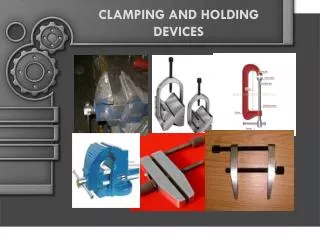
Clamping Arm
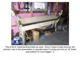
This is the 8’ metal bending brake we used. Since I forgot to take pictures, the pictures I use in this presentation to describe what I’m doing are from an 18” brake. Just pretend it’s much bigger! .

Clamping Arm
E N D
Presentation Transcript
This is the 8’ metal bending brake we used. Since I forgot to take pictures, the pictures I use in this presentation to describe what I’m doing are from an 18” brake. Just pretend it’s much bigger!
These are the two levers you’ll use. You really need one person on each side. There is an adjustment on each side to account for material thickness. Bending Arm Clamping Arm
A closer look. I put this picture in because it is the only other one I took. You can see the edge of the foot.
If you look close you can see a piece of aluminum in there now. You can also see the foot cover we added. I always pictured the big flat side of the bending table as the part that sat flat against the piece being bent – that’s not it at all – it’s the edge that makes the bend. I guess that’s why I’ve always had a hard time visualizing how that worked. Bending Edge Aluminum Piece Foot Edge Foot Cover
For my next spars I’m going to do it a little differently. This is what I’d recommend: Make a template out of 3/4” plywood and MDF. Use your rib and trace the pattern onto the template.
Mark the flange on the top of your spar web (Note this piece is 7-1/2” x 3” to use as a test piece for the false spar behind the fuel tank. The top of the spar web is on the left in this photo.)
Slide you spar web into the brake leaving on the top flange side out for the first bend.
Position your spar web so that you flange line is just showing under the brake foot.
Rock the bending arm up and down as your work your bend in. (Note: when using an 8’ brake it will take about 10 times of the rocking action to get a full 90 degree bend in.)
Check your angle using your template (note: you can also make a small angle template out of scrap metal if you don’t make a rib template)
Remove your spar web from the brake and place it flat. Position your template (or rib) so the top is tight to the top flange. Mark the bottom of your template (or rib) at each end of the spar.
Position the spar web so only the bottom flange is under the brake foot for the second bend. (Note: for the 8’ brake that I used we found that the line needed to be just hidden, sliver showing, to properly locate the bend.)
Check your angle using your template. (Note: We were able to just eyeball this bend since it’s close to a 90 degree bend)
Check your spar for a tight fit using your template or actual rib.
Checking nose rib fit to main spar test piece with simulated top skin.
Checking nose rib fit to main spar test piece with simulated bottom skin.
Just for kicks here’s how far my first main spar webs were off. Make sure you use a full sized rib to make your template or mark your spar bends!
You can see what a bump it would leave if your spar is too big.