Download
1 / 34
340 likes | 354 Vues
Explore petrological-thermomechanical modeling of geodynamic processes with examples and methodology. Learn about density mapping, latent heating, volume changes, and numerical solutions for modeling such processes.

E N D
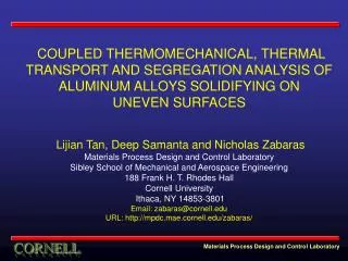
Petrological-thermomechanical modeling of geodynamic processes: examples methodology and Taras V. Gerya1, James A.D. Connolly1,David A. Yuen2 1 ETH– Zurich 2 University of Minnesota, Minneapolis
1. Maping of density and enthalpy in the P-T space Gibbs free energy minimization H= H (Pressure, Temperature, Composition, Mineralogy) = (Pressure, Temperature, Composition, Mineralogy) (Gerya et al., 2001, 2004, Connolly & Petrini, 2002, Vasiliev et al., 2004)
2. Latent heating Latent heating is implemented via effective heat capacity (Cp) and effective adiabatic heating (Qp)computed numerically from the enthalpy and density maps standard thermodynamic relations Cp= (H/T)P Qp= (DP/Dt)[1- (H/P)T] Lagrangian temperature equation Cp(DT/Dt) = (kT/x)/x + (kT/z)/z + Qp + Qshear + Qradioactive 3. Volume changes Volumetric effects of phase transformations are taken into account in both the momentum and the continuity equations Lagrangian continuity equation for compressible flow D(ln)/Dt + div(v) = 0
Method of numerical solution original 2-D and 3-D single- & multi-processor C-codes I2, I3, I2VIS, I2ELVIS, I2IOMP, I3MG (Gerya et al., 2000; Gerya & Yuen, 2003) Staggered grid Combination of finite-differences, on staggered grid , and marker-in-cell technique Marker technique Finite differences T P1 P2 Dx дP/дx = (P2-P1)/Dx
ALL-IN-ONE TOOLBOX The software fit advances in hardware technology - Work stations: n104nodes, n107markers Supercomputers: n107nodes, n1010markers in visualization technology - ultra-highspatial resolution for very largenumerical models The software accounts for variable tectonic environment phase transformations visco-elasto-plasticrheology erosion/sedimentation processes Air Sea water Accretion wedge 10 km Subducting plate
Example 1 Cold plumes
Mixed and unmixed cold plumes 10 million markers (with slab fluids signatures) (with crustal melts) Gerya et al. (2006)
Internal structure of mixed plumes to 1 m scale 10 billion markers original view zoom: 30 zoom: 3 zoom: 100 zoom: 300 zoom: 10
zoom: 30 1 km 1 km Obata (2000) Do we see cold plumes?
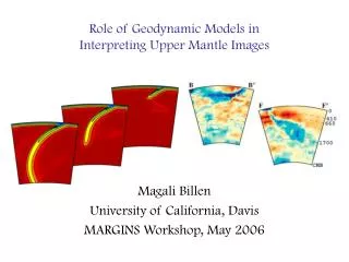
Numerical tomographic model Do we see cold plumes? Seismic tomography Gerya et al. (2006) Zhao et al. (1992)
Example 2 Intrusion dynamics
Intrusion of magmatic pipe into the crust 100oC 200oC 300oC 400oC
Intrusion of magmatic pipe into the crust 100oC 200oC 300oC 400oC
Intrusion of magmatic pipe into the crust 100oC 200oC 300oC 400oC
Intrusion of magmatic pipe into the crust 100oC 200oC 300oC 400oC
Intrusion of magmatic pipe into the crust 100oC 200oC 300oC 400oC
Intrusion of magmatic pipe into the crust 100oC 200oC 300oC 400oC
Intrusion of magmatic pipe into the crust 100oC 200oC 300oC 400oC
Intrusion of magmatic pipe into the crust 100oC 200oC 300oC 400oC
Intrusion of magmatic pipe into the crust 100oC 200oC 300oC 400oC
Intrusion of magmatic pipe into the crust 100oC 200oC 300oC 400oC
Intrusion of magmatic pipe into the crust 100oC 200oC 300oC 400oC
Intrusion of magmatic pipe into the crust 100oC 200oC 300oC 400oC
Intrusion of magmatic pipe into the crust 100oC 200oC 300oC 400oC
Intrusion of magmatic pipe into the crust 100oC 200oC 300oC 400oC
Intrusion of magmatic pipe into the crust 100oC 200oC 300oC 400oC
Intrusion of magmatic pipe into the crust 100oC 200oC 300oC 400oC
Intrusion of magmatic pipe into the crust 100oC 200oC 300oC 400oC
Intrusion of magmatic pipe into the crust 100oC 200oC 300oC 400oC
Intrusion of magmatic pipe into the crust 100oC 200oC 300oC 400oC The End