Download
1 / 57
830 likes | 2.12k Vues
CHEE 321: Chemical Reaction Engineering Module 3: Isothermal Reactor Design (Chapter 4, Fogler). Module 3: Isothermal Reactor Design. Topics to be covered in this module 4-Step Algorithm for solving reactor design problem CSTR in-series

E N D
CHEE 321: Chemical Reaction EngineeringModule 3: Isothermal Reactor Design(Chapter 4, Fogler)
Module 3: Isothermal Reactor Design Topics to be covered in this module • 4-Step Algorithm for solving reactor design problem • CSTR in-series • Damkohler Number (Application to design of CSTR-in-series) • Pressure drop in packed bed reactor • Ergun equation • Pressure drop as a function of catalyst weight • Microreactors • Semi-Batch Reactor
“In perhaps no area of engineering is mere formula plugging more hazardous; the number of physical conditions that can arise appear infinite, and the chances of a simple formula being sufficient for the adequate design of a real reactor are vanishingly small.” From Fogler, Chapter 4
General Algorithm for Solving Isothermal Reactor Problems • General Mole Balance Equation (GMBE) • Rate Laws • Write down rate law in terms of limiting reactant • Stoichiometry • relate concentration to volume and number of moles (for batch reactors) or to volumetric flow rate and molar flow rate (for flow reactor) • Relate volume or volumetric flow rate to conversion (X), pressure and temperature • Combine • Substitute rate law and stoichiometry in to the GMBE
Class Problem-4 It is being considered that the following gas-phase reaction be carried out in a CSTR: A + 2B 4C The reactor will be operated isobarically and isothermally. The rate law for the reaction is given as: (-rA)=k CACB where, k = 8 L/mol-min at the operating temperature. The total feed volumetric flow rate to the reactor at operating temperature and pressure is 10 L/min. The feed consists of A, B and an inert (I). The feed molar flow rates are FA0= FB0= 1 mol/s and FI0=2 mol/s. • Calculate the volume of reactor required to achieve 80% conversion of the limiting reactant. • If all other conditions are kept constant (including total volumetric flow rate) but no inert is present in the feed, calculate the reactor volume required to achieve 80% conversion of limiting reactant
Damkohler Number (Da) Da is a dimensionless number that can provide a quick estimate of the degree of conversion in continuous flow reactors. First-order reaction Second-order reaction Da 0.1 usually results in conversion less than 10% Da 10 usually results in conversion greater than 90%
CAO X=0 v0 CA2 X=X2 CA1 X=X1 V1 ; k1 V2 ; k2 CSTR in series Mole Balance on CSTR-1 Liquid-phase (v = v0), first-order reaction Mole Balance on CSTR-2
CAO X=0 v0 CAn X=Xn CA n-1 X=Xn-1 V V V V V All CSTR’s are operated at same temperature [ k is same in all reactors] n-Equal Sized CSTR in series
V V V n-Equal Sized CSTR in Parallel vo/n C1 X=X1 vo/n What is the “conversion” of the mixed stream ? CA2 X=X2 CAO X=0 v0 vo/n CA3 X=X3 X = Xmix vo/n CAn X=Xn V
‘n’ Equal-sized CSTRs - Which is a better configuration? Parallel or Series If you had n-equal sized reactors available and had the option of setting them in series or parallel, which configuration would you choose to achieve maximum conversion for a first-order reaction occurring in liquid phase? Justify your choice?
in mol/time·mass of catalyst Solid Catalyzed Reactions • Reaction rates are usually expressed in terms of mass of catalyst loading. • The design equations can be derived in a manner similar to those for homogeneous reactors - by using mass (w) instead of volume (V). • Examples of solid catalyzed reactions: • Steam Methane Reforming (SMR) for HYDROGEN production • Conversion of NOx and CO in automobile catalytic converter • Styrene production
FA FAO w w+w Mass of catalyst = w General Mole Balance for Packed Bed Reactors Input - Output + Gen = Accumulation
Pressure Drop in Packed Bed Reactors • Flow of fluids through packed beds is accompanied by substantialpressure drop across the bed. • From reaction perspective, do we need to account for pressure drop in packed bed reactors ? The answer depends on the type of reaction • For liquid-phase reactions, small changes in pressure does not affect concentration and consequently does not affect the reaction rates. • However, for gas-phase reactions, the concentrations are a function of pressure. Reduction in pressure implies reduction in concentration and, consequently, a reduction in reaction rates.
Concentration does not depend on pressure. No need to calculate pressure to solve for conversion Relationship between concentration and pressure (ri) = k(T) f(Concentration) Case I: Liquid phase reactions v = vO =constant Case II: Gas phase reactions Inlet Conditions
(P/PO) may vary along the reactor length Relationship between concentration and pressure Case II: Gas phase reactions (cont.) For isothermal reactor (ri) = k(T) f(Concentration)
Pressure Drop in an Isothermal PBR – Our Approach Ultimately, we want to write two coupled differential equations that describes how the two variables - conversion (X) and pressure (P) - change with reactor length or mass of catalyst packed Variation of conversion with catalyst weight From GMBE Variation of pressure with catalyst weight Next, we will review equation describing pressure drop in packed beds
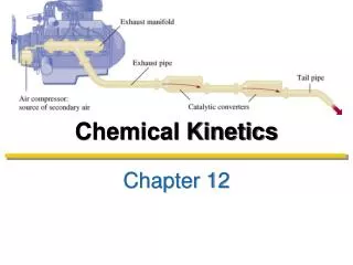
Laminar (NRE < 1) Turbulent (NRE > 1000) Differential equation for pressure drop in bed of spherical packing Pressure Drop in Packed Bed Reactors ERGUN equation for pressure drop in a packed bed:
Varies with operating condition and reaction mixture Pressure Drop in Packed Bed Reactors • In the above equation, some of the parameters are: • characteristic of the packing [porosity (f), particle (Dp)] • characteristic of fluid property [viscosity (m), density (r)] • characteristic of operating parameters [mass velocity (G)] Fixed for a given packed bed • The packing characteristics are usually considered to be invariant with respect to reactor length. • This leaves us with the following parameters to be evaluated as a function of reactor length • the fluid properties: viscosity (m) and density (r) • the operating parameterG
Evaluating terms in Ergun equation Superficial Mass velocity (G) G is the mass flow rate per unit area (kg/m2-s). Here, u and u0are velocities (in m/s) NOT to be confused with volumetric flow rate (v) For a reactor with a constant cross-section, G is constant. Thus, if G is known at inlet it need not be evaluated at any other reactor position z
Evaluating terms in Ergun equation Viscosity (m) Viscosity of gases are weak function of pressure. We can assume the gas mixture viscosity to be independent of pressure. The viscosity of gases depend on the mixture composition. In a reactor, mixture composition will change, the gas mixture viscosity will also change. Density (r) • Density of gases depend on pressure. • There are two ways of handling the pressure term: • in terms of inlet density, P/Po, T/To • in terms of local P, T and composition
Pressure Drop in PBR – Simplified functional form If numerical method is applied to solve for differential equation, a simpler and more elegant approach is to calculate density at any given position (z) in the reactor using ideal gas law and local conditions: Average Molecular Weight of gas mixture where,
Pressure Drop in an Isothermal PBR Our GOAL is to write two coupled differential equations that describes how the two variables - conversion (X) and pressure (P) - change with reactor length or mass of catalyst packed Variation of conversion with catalyst weight From GMBE Variation of pressure with catalyst weight
Ac z Pressure Drop as a Function of Catalyst Mass (w) For a tubular reactor of cross-sectional area (Ac) and packed with a catalyst density (rc) over a length z, the mass of the catalyst can be written as: Differentiating the above equation, we get or
Pressure Drop in terms of Catalyst Mass (W) – Cont. Substituting, into We get We do not yet have a differential equation for pressure in terms of conversion X
Pressure Drop in terms of Catalyst Mass (W) – Cont. The pressure drop equation is Recall, where, Also, we know that Therefore, Fi = f(X) and FT= g(X) r(X) denotes r is a function of X
f1(P,T, X) f2(P,T, X) Coupled Differential Equation for Packed Bed Reactors
Membrane – Terminologies Membrane: A material that allows selective permeation (or passing through) of certain molecules (species). Permeate: The part of the fluid stream that passes through the membrane. Retentate: The part of the fluid stream that does not pass through the membrane. Permeate Membrane Feed Retentate Permeate Schematic representation of a membrane separation process
Membrane Reactors – What and Why? • Usually in a chemical process, the separation of wanted and unwanted species are carried out in a separation vessel downstream of a reactor. • Membrane reactor allows the separation and reaction processes to occur simultaneously and in a single-vessel. • Catalytic membrane reactor can be used to increase the yields of products from reactions that are thermodynamically limited, i.e. from reversible reactions. • Catalytic membrane reactors can be classified into two categories: • Inert Membrane Reactor with Catalyst on Feed Side • Catalytic Membrane Reactor
Inert Membrane Reactor with Catalyst on Feed side (IMRCF) Permeate Membrane Feed Catalyst Permeate • reaction is effected by the catalyst present as a pellet or packing. • membrane is inert and merely allows selective permeation of a particular species. • the feed side can be treated simply as a packed bed reactor
Catalytic Membrane Reactor (CMR) Permeate Membrane Feed Permeate • reaction occurs on the membrane surface which acts as a catalyst • membrane is not inert and allows both the selective permeation of a particular species and the reaction catalysis • the feed side can be treated simply as a plug flow reactor, if there are no packings.
Membrane Reactor: General Mole Balance RC FB Reaction: C3H8 C3H6+ H2 ABC FA FC Membrane is permeable to C only GMBE on C GMBE on A GMBE on B RC = rate of permeation
Membrane Reactor: Permeation Rate RC FB FA FC RC = rate of permeation moles/cm3-s = f (CA) or f (PA) • Permeation rates are usually determined experimentally. For example, hydrogen permeation through Palladium membrane is given by following equation:
Micro-reactors: It is all about scale 20 m? Conventional Chemical Plant Microreactor
Micro-reactors: Introduction Oregon State University— Fractal MECS Devices • Generally, we mean: • Fluid chemical reactants • Microscale ducts, chambers • High surface area/vol ratio • Small volume flowrates • Precise parameter control • Well-suited for: • Small-scale output • In-situ/portable reactors • High efficiency (yield, thermal efficiency) • High precision • e.g., Lab-on-a-chip tech Micro-Space Chemistry Lab– Various Microreactors
Micro-channel Reactors • Reacting mixture flows through the channels • Catalyst coated on channel surface • Salient features of micro-channel reactors • High heat transfer rate • High mass transfer rate • Large reaction area per unit volume • Low pressure drop
Power to Application The Role of the Reactor“From Well to Wheel” Methanol Supply Small Fuel Cell e.g. carbon recycling plant Local Storage & Transport Separate H2 Reforming Reactor CH3OH + H2O CO2 + 3H2 e.g. a small tank e.g. palladium membrane
500 mm 30 mm Micro-channel reactor: alumina substrate
….Testing Catalyst Activity Microchannel reactor assembly Microchannels on a wafer
Computational Modelling (Above) Fluid at room temperature enters a heated microchannel and reaches target T=470K in ~10μm. (Above) Fluid enters microchannel and reaches fully developed (FD) flow in ~10 μm. • Computational simulations have been run to predict channel flow. • Results generally show reactants are quick to reach target temperature. • (Above) Results show flow development in a cross-section of a channel inlet.
GMBE for a Catalyst Coated Microchannel Reactor Feed Catalyst Coating Square X-Section Circular X-Section Derivation to be provided in class