Network-on-FPGA
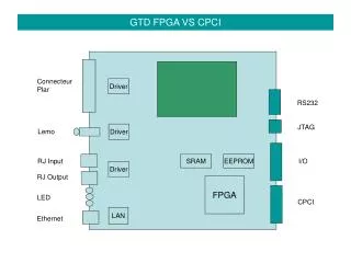
Network-on-FPGA. Aleksander Ś lusarczyk. Network-on-FPGA. Network topologies routing Data processor mMIPS network interface. uP. NI. uP. Mem. IF. Network. Easy to implement Easy to use No software assistance required Reliable No scheduling/routing. Dally’s network.

Network-on-FPGA
E N D
Presentation Transcript
Network-on-FPGA Aleksander Ślusarczyk
Network-on-FPGA • Network • topologies • routing • Data processor • mMIPS • network interface uP NI uP Mem IF
Network • Easy to implement • Easy to use • No software assistance required • Reliable • No scheduling/routing
Dally’s network • Torus topology • E-cube routing • Unidirectional links • deadlock-free (2 virtual channels per link)
H D T 16b 16b 16b Sub-router
Dally’s network • Guaranteed delivery, deadlock-free • no software required, reliable out-of-the-box • Fixed route • impossible congestion avoidance, load balancing • no timing guarantees
Topologies - Mesh • Bidir links (double the connections) • Asymetric at edges
Topologies - Tree • One route • Bidir links • Top-level nodes overloaded
1 [2,5] [1,2] [1,1] [3,5] 3 2 [4,5] 4 5 [1,2] [3,5] [1,4] Routing • E-cube • Interval • Range of addresses assigned to output port • Deadlock-free labellings for many topologies
t \ o O1 O2 O3 t1 I1 t2 I2 t3 I1 O2 I1 O1 I3 O3 I2 Route tables • Time slots • In a time slot one connection active • Compile-time fixed • Scheduling required • Contention-free • Guaranteed timing
Routing - Dynamic • Header contains routing information • E.g. streetsign: “goto x, turn left, goto y, turn right, … ” • Determined by user application or Network Interface (e.g. routing table) • Intermediate router determines best route
Data processor • Starting point – mMIPS developed for OGO • pipelined • 28 instructions • separate D/I memory • synthesizable SystemC
IM DM NI mMIPS Data: 0x8000000 Ctl: 0x8000004 address send data_rdy send_rdy Network interfacing • Memory mapped network device
I$ D$ NI NI+ RAM IM DM MEMIF mMIPS Memory • Data and instruction cache • Currently : local main memory • Plan : network access to memory
Implementation mMIPS : 600 slices Cache : 2 x 300 slices Router : 500 slices N.I. : 100 slices + : 1800 Virtex2 3000 : 15,000 slices + 200 KB RAM @ 30-50 MHz
Software • LCC compiler for mMIPS (Sander Stuijk) • Communication library (Mathijs Visser) • C send/receive primitives (blocking/non-blocking) • networked JPEG
Software for the Network-on-FPGA Mathijs Visser (student E) January 2004 , version 1.0
Introduction Goals: • Create a communications library for C.Improve the programmability of the mMips network • Create and test a multi processor applicationVerify HW and SW correctness Context: • Courses for twaio’s • Network-on-Chip flagship
Overview • Current software tools • The C compiler (lcc) • C communications library • The simulator (SystemC) • Simple C debugging library • Multi processor applications • Two examples • Design process & FPGA demonstration • Summary
C compiler (LCC) • Advantages • Designed for retargetability • Ported by Sander Stuijk for mMips • Different memory layouts supported without recompilation • Disadvantages • ANSI/POSIX libraries not implemented • No debugging information • Ongoing test process
mMips communication revisited Memory mapped communication • Request transmission of Data_word • Check whether Data_word valid? • Set destination node address Status_word Data_word • Contains received data, • Location to write outgoing data to Max. physical address 0x0000 32 bits
C communications library Goal Simplify inter-processor communications for the C programmer (= user). Constraints • Time: Design and test in around 40 hours • Interface: Easy to use, encapsulate HW details • ROM memory: Should require less than 1kbyte • Adhere to a well know standard.
C communications library Possible communication scheme:Message passing • Blocking send and receive • Non-blocking send (= try) and receive (= peek) Possible implementation: ¥ ¥Retry count as optional parameter
C communications library Advantages of Message Passing • Directly supported by hardware • Small code base (meets memory constraints) • Easy to implement (meets time constraints) • Forms basis for more complex protocols • Only two operations (meets constraints for simplicity) • Uses message passing (= a standard, as required)
Simulator (SystemC) System level design tool • C++ Class Libraries forhardware constructs, such as adders • SystemC model of the mMips network (Alex) • Standalone executable can be generated
Simulator (SystemC) Important debugging tool • VCD tracings • Memory dumps (ROM & RAM) • Spy module: • Spy on instruction pointer (IP) & communication • Watch read/writes on specific addresses • Stop simulation when IP at specific address • Additional options…
C library for debugging Desirable because: • LCC cannot generate debugging info • No CRT/console, so no printf()
C library for debugging Solution to debugging problem? • Implements a printf()-variant • Writes output to memory • Useful for both Simulator and FPGA implementation. FPGA memory 0x8000 Program data and Stack - Reserved - 0x4000 Output of printf() is stored here Instructions 0x0000
Multi processor applications(for the mMips network) • Two examples • Design process & FPGA demonstration
Multi processor applications • Two applications were developed • Multi processor JPEG decoder • “Gossip”: a small message circulates the network • Both resulted in improvements of both compilerand mMips • “Gossip” application & design process will be demonstrated • Next slide: some words on the JPEG decoder
JPEG decoder 2x2 mMipsNetwork Input:JPEG image Output:BITMAP image
JPEG decoder Not finished yet… • Large: ± 500 lines of code • Limited debugging facilities • Long simulation times:2 hours for 16x16 image • Discovery of compiler or hardware issues 2x2 mMipsNetwork Input:JPEG image Output:BITMAP image
JPEG decoder Finish the JPEG decoder Because… • This complex algorithm is a good test case • Good example of a realistic application
Demonstration Hardware “Gossip” application: (send a short message over the network) Node 0 (x0y0) Node 0 (x1y1) Message (18 bytes):“I know something!” Node 1 (x1y0) Node 2 (x0y1)
“Gossip”: from idea to hardware • Create the C program • All nodes are identical except for their node ID • Node ID: pointer to address in user_data segment. • Compilation • Compile one node (lcc) • Separate code anddata using ashell script • Insert user_data Program data and Stack User data File withUser data(e.g. Node ID) 3 Program code 2 1 Node 0
“Gossip”: from idea to hardware • Use the SystemC simulator to test & debug • Upload to and run in FPGA Program data and Stack User data 3 Program code 2 1 Node 0
Summary • C Communications library (Message passing) implemented & tested • Test applications have lead to improvementsin Compiler, Debugging facilities and hardware • Future work: • A working JPEG decoder • Improved debugging capabilities