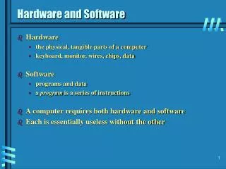
Week 4: Hardware and Software Architecture
Week 4: Hardware and Software Architecture. General Concepts Memory Addressing IA-32 Processor Architecture IA-32 Memory Management Components of an IA-32 Microcomputer Input-Output System. Chapter Overview. Basic microcomputer design Instruction execution cycle Reading from memory


Week 4: Hardware and Software Architecture
E N D
Presentation Transcript
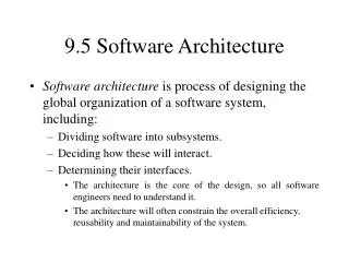
General Concepts Memory Addressing IA-32 Processor Architecture IA-32 Memory Management Components of an IA-32 Microcomputer Input-Output System Chapter Overview
Basic microcomputer design Instruction execution cycle Reading from memory How programs run General Concepts
CPU clock synchronizes CPU operations control unit (CU) coordinates sequence of execution steps ALU performs arithmetic and bitwise processing General ConceptsBasic Microcomputer Design
synchronizes all CPU and BUS operations machine (clock) cycle measures time of a single operation clock is used to trigger events General Concepts Clock
Clock rate Number of clock pulses per second Ex. 2.8 GHz processor = 2,800 million clock cycles/sec CPU time CPU clock cycles for a program Clock cycle time or CPU clock cycles for a program / Clock rate General Concepts CPU Performance
IC – Instruction count CPI – Clock cycles per instruction = CPU clock cycles for a program / IC CPU time = IC CPI Clock cycle time or =IC CPI / Clock rate General Concepts CPU Performance (Cont.) Clock rate – Hardware technology and organization CPI – Organization and instruction set architecture IC – Instruction set architecture and compiler technology
Total number of CPU clock cycles CPU time Overall CPI General Concepts CPU Performance (Cont.)
Ex. Suppose we have made the following measurement: Frequency of FP operations = 25% Average CPI of FP operations = 4.0 Average CPI of other instructions = 1.33 Frequency of FPSQR = 2% CPI of FPSQR = 20 Assume that the two design alternatives are to reduce the CPI of FPSQR to 2 or to reduce the average CPI of all FP operations to 2. Compare these two design alternatives. General Concepts CPU Performance (Cont.)
Speedup = or General Concepts CPU Performance (Cont.) Amdahl’s Law: The performance improvement to be gained from using some faster mode of execution is limited by the fraction of the time the faster mode can be used.
Ex. Suppose FPSQR is responsible for 20% of the execution time of a critical benchmark on a machine. One proposal is to add FPSQR hardware that will speed up this operation by a factor of 10. The other alternative is just to try to make all FP instructions run faster; FP instructions are responsible for a total of 50% of the execution time. The design team believes that they can make all FP instructions run two times faster with the same effort as required for the fast square root. Compare these two design alternatives. General Concepts CPU Performance (Cont.)
Ex. CPU1 – compare & branch instructions are separate CPU2 – compare & branch taking 1 instruction Cycle times: CLK2 = 1.25 CLK1 Conditional branch: 2 cycles Other instruction: 1 cycle On CPU1, 20% of all instructions executed are branch instructions. Which CPU is better? General Concepts CPU Performance (Cont.)
Solution: CPI1 = 0.2 * 2 + 0.8 * 1 = 1.2 CPU time1 = IC1 * 1.2 * CLK1 = 1.2 * IC1 * CLK1 Clock cycle time CLK2 is 1.25 * CLK1, since CPU1 has a clock rate that is 1.25 times higher. Compares are not executed in CPU2, so 20%/80% or 25% of the instructions are now branches taking 2 clock cycles. The rest 75% of the instructions are taking 1 clock cycle. So, CPI2 = 0.25 * 2 + 0.75 * 1 = 1.25 CPU time2 = IC2 * CPI2 *CLK2 = 0.8*IC1 * 1.25 * (1.25*CLK1) = 1.25 * IC1 * CLK1 General Concepts CPU Performance (Cont.)
MIPS – millions of instructions executed per second MFLOPS – millions of floating point operations executed per second General Concepts CPU Performance (Cont.)
Fetch Decode Fetch operands Execute Store output General ConceptsInstruction Execution Cycle
Pipelining makes it possible for processor to execute instructions in parallel Instruction execution divided into discrete stages General ConceptsMulti-Stage Pipeline Example of a non-pipelined processor. Many wasted cycles.
More efficient use of cycles, greater throughput of instructions: General ConceptsPipelined Execution For k states and n instructions, the number of required cycles is: k + (n – 1)
When one of the stages requires two or more clock cycles, clock cycles are again wasted. General ConceptsWasted Cycles (pipelined) For k states and n instructions, the number of required cycles is: k + (2n – 1)
A superscalar processor has multiple execution pipelines. In the following, note that Stage S4 has left and right pipelines (u and v). General ConceptsSuperscalar For k states and n instructions, the number of required cycles is: k + n
Pipelining isn’t usually as simple as starting a new instruction every cycle Instructions may share datapath resources (e.g. the ALU, ports for writing to registers) Pipelining can be “stalled” Waiting for I/O to complete Waiting for hardware resources to free up Waiting for the result of one computation before another can be completed General ConceptsPipelining Hazards
A pipeline cannot accommodate a possible combination of instructions due to resource conflicts Example: Shared single-memory pipeline for data and instructions A data-memory reference may conflict with a later instruction reference General fix for a structural hazard is to stall one of the conflicting instructions until the hazard is clear. A stall is commonly called pipeline bubble General Concepts Structural Hazards
Suppose there is only one memory port. 1 2 3 4 5 6 7 LOAD IF ID EXE MEM WB Ins. i + 1 IF ID EXE MEM WB Ins. i + 2 IF ID EXE MEM WB Ins. i + 3 stall IF ID EXE … Ins. i + 4 IF ID … Ins. i + 5 IF … General Concepts Structural Hazards No instruction is initiated on clock cycle 4 since the LOAD instruction effectively steals an instruction-fetch cycle
Suppose there is one memory port. Data references constitute 40% of the execution. The ideal CPI of the pipelined machine is 1, ignoring the structural hazard. Assuming that the machine with the structural hazard has a clock rate that is 1.05 times higher than the clock rate of the machine without the hazard. Which machine is faster, with or without pipelining? By how much? General Concepts Cost of Structural Hazards Average CPU time with hazard = CPI * Clock cycle time = (1+0.4*1) * Clock Cycle time ideal/1.05 = 1.3 * Clock Cycle time idea
Occurs when the pipeline changes the order of read/write access to operands so that the order differs from the order on an unpipelined machine. Classifications of Hazards Assume instruction i occurs before j: RAW (Read After Write) j tries to read a source before i writes it. WAR (Write After Read) j tries to write a destination before it’s read by i. WAW (Write After Write) j tries to write an operand before it is written by i. General Concepts Data Hazards
RAW — gets old value Consider the following sequence: ADD R1, R2, R3 — Reg[R1] <– Reg[R2]+Reg[R3] SUB R4, R1, R5 — Reg[R4] <– Reg[R1]-Reg[R5] ADD IF ID EXE MEM WB SUB IF ID EXE MEM WB The result of the ADD is needed for the SUB, but the ADD may not be done processing when the SUB is ready for the result R1 is written R1 is read General Concepts Data Hazards
WAW — write in the wrong order Note: Presents only in pipelines that write in more than one pipe stage or allow an instruction to proceed even when a previous instructions is stalled Suppose: 1. Data memory access takes two pipe stages 2. We could move WB for an ALU operation into the MEM stage Consider the following sequence: LOAD R1, 0(R2) — Reg[R1] <– Mem[0+Reg[R2]] ADD R1, R2, R3 — Reg[R1] <– Reg[R2]+Reg[R3] LOAD IF ID EXE MEM1 MEM2 WB ADD IF ID EXE WB General Concepts Data Hazards
WAR — incorrectly gets new value Note: Occurs when some instructions write results early in the instruction pipeline stage, and some instructions read a source late in the pipeline. Suppose: 1. Data memory access takes two pipe stages 2. We could move WB for an ALU operation into the MEM stage 3. Read operands late Consider the following sequence: STOR 0(R1), R2 — Mem[0+Reg[R1]] <– Reg[R2] ADD R2, R3, R4 — Reg[R2] <– Reg[R3]+Reg[R4] STOR IF ID EXE MEM1 MEM2 WB ADD IF ID EXE WB General Concepts Data Hazards
Some fixes Forwarding -- Always writing results back to the ALU latches immediately for use by next operation Compiler rescheduling -- Try to reschedule operations so that operations are not immediately followed by dependent ones General Concepts Data Hazards
Branch penalties: the result of a condition evaluated during a pipeline invalidates work currently in the pipeline Can stall the pipeline Can try to predict the direction of the branch and execute relevant instructions -- additional rollback penalty if wrong Most branches are not taken -- requires study of particular programs Interrupts make things difficult More complex to restart a pipeline General Concepts Control Hazards
Multiple machine cycles are required when reading from memory, because it responds much more slowly than the CPU. The steps are: address placed on address bus Read Line (RD) set low CPU waits one cycle for memory to respond Read Line (RD) goes to 1, indicating that the data is on the data bus General ConceptsReading from Memory
High-speed expensive static RAM both inside and outside the CPU. Level-1 cache: inside the CPU Level-2 cache: outside the CPU Cache hit: when data to be read is already in cache memory Cache miss: when data to be read is not in cache memory. General ConceptsCache Memory
OS can run multiple programs at the same time. Multiple threads of execution within the same program. Scheduler utility assigns a given amount of CPU time to each running program. Rapid switching of tasks gives illusion that all programs are running at once the processor must support task switching. General ConceptsMultitasking
Interpreting memory address Addressing mode Operations in the instruction set Type and size of Operand Encoding an instruction set Memory Addressing
Two conventions for ordering the bytes within a word Big Endian: The most significant byte of a variable is stored at the lowest address Little Endian: The least significant byte of a variable is stored at the lowest address Ex: double word 12345678h in memory Little Big Memory AddressingInterpreting Memory Address
In Big Endian address, the address of a dataum is the address of the most significant byte In Little Endian address, the address of a dataum is the address of the least significant byte Access to an object larger than a byte must be aligned Ex. An object of size N is accessible at address A such that A mode N = 0 Memory Run faster Memory AddressingInterpreting Memory Address
Load Conditional branch Compare Store Add And Sub Move register-register Call Return Memory AddressingOperations in The Instruction Set
8, 16, 32 bit integers 64-bit FP data Memory AddressingType and Size of Operands
Encoding affects Size of the compiled program Implementation of CPU Operation is typically specified in a field called opcode Memory AddressingEncoding an Instruction Set
Three popular choices: Variable Allow all addressing mode and operations Try to use as few bits as possible Amount of work varies First 4 bits – addressing mode Second 4 bits – register used Memory AddressingEncoding an Instruction Set …
Three popular choices: Fixed Combines the operation and the addressing mode into the opcode Easy to decode Instruction length is fixed Memory AddressingEncoding an Instruction Set
Three popular choices: Hybrid Reduce variability in size and work Provide multiple instruction length Memory AddressingEncoding an Instruction Set
Modes of operation Basic execution environment Floating-point unit Intel Microprocessor history IA-32 Processor Architecture
Protected mode native mode (Windows, Linux) Real-address mode native MS-DOS System management mode power management, system security, diagnostics IA-32 Processor ArchitectureModes of Operation • Virtual-8086 mode • hybrid of Protected • each program has its own 8086 computer
Addressable memory General-purpose registers Index and base registers Specialized register uses Status flags Floating-point, MMX, XMM registers IA-32 Processor ArchitectureBasic Execution Environment
Protected mode 4 GB 32-bit address Real-address and Virtual-8086 modes 1 MB space 20-bit address IA-32 Processor ArchitectureAddressable Memory
IA-32 Processor ArchitectureGeneral-Purpose Registers Named storage locations inside the CPU, optimized for speed.
Use 8-bit name, 16-bit name, or 32-bit name Applies to EAX, EBX, ECX, and EDX IA-32 Processor ArchitectureAccessing Parts of Registers
Some registers have only a 16-bit name for their lower half: IA-32 Processor ArchitectureIndex and Base Registers