Download

1 / 78
780 likes | 917 Vues
This lecture explores the fundamental differences between combinational and sequential logic in digital circuits. It covers key concepts such as inputs, clock edges, and output behaviors in both types. The presentation also introduces important components like decoders, multiplexers, and adders, explaining their functions and applications. Additionally, techniques for implementing Boolean functions with multiplexers are discussed, along with practical examples. Ideal for computer science students looking to deepen their understanding of logic design.

E N D
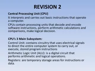
Lecture 26 Revision Problems 2 Prof. Sin-Min Lee Department of Computer Science
Example of combinational and sequential logic • Combinational: • input A, B • wait for clock edge • observe C • wait for another clock edge • observe C again: will stay the same • Sequential: • input A, B • wait for clock edge • observe C • wait for another clock edge • observe C again: may be different A C B Clock
Basically • Combinational: • No internal state (or memory or history or whatever you want to call it) • Output depends only on input • Sequential: • Output depends on internal state • Probably not going to be on this midterm since formal lecture on it started last Thursday.
Some commonly used components • Decoders: n inputs, 2noutputs. • the inputs are used to select which output is turned on. At any time exactly one output is on. • Multiplexors: 2n inputs, n selection bits, 1 output. • the selection bits determine which input will become the output. • Adder: 2n inputs, 2n outputs. • Computer Arithmetic.
Multiplexer • “Selects” binary information from one of many input lines and directs it to a single output line. • Also known as the “selector” circuit, • Selection is controlled by a particular set of inputs lines whose # depends on the # of the data input lines. • For a 2n-to-1 multiplexer, there are 2n data input lines and n selection lines whose bit combination determines which input is selected.
MUX Enable 2n Data Inputs Data Output n Input Select
Remember the 2 – 4 Decoder? Sel(3) S1 Sel(2) Sel(1) S0 Sel(0) Mutually Exclusive (Only one O/P asserted at any time
4 to 1 MUX DataFlow D3:D0 Dout 4 Control 4 2 - 4 Decoder Sel(3:0) 2 S1:S0
4-to-1 MUX (Gate level) Control Section Three of these signal inputs will always be 0. The other will depend on the data value selected
Multiplexer (cont.) • Until now, we have examined single-bit data selected by a MUX. What if we want to select m-bit data/words? Combine MUX blocks in parallel with common select and enable signals • Example: Construct a logic circuit that selects between 2 sets of 4-bit inputs (see next slide for solution).
Example: Quad 2-to-1 MUX • Uses four 4-to-1 MUXs with common select (S) and enable (E). • Select line chooses between Ai’s and Bi’s. The selected four-wire digital signal is sent to the Yi’s • Enable line turns MUX on and off (E=1 is on).
Implementing Boolean functions with Multiplexers • Any Boolean function of n variables can be implemented using a 2n-1-to-1 multiplexer. A MUX is basically a decoder with outputs ORed together, hence this isn’t surprising. • The SELECT signals generate the minterms of the function. • The data inputs identify which minterms are to be combined with an OR.
Example • F(X,Y,Z) = X’Y’Z + X’YZ’ + XYZ’ + XYZ = Σm(1,2,6,7) • There are n=3 inputs, thus we need a 22-to-1 MUX • The first n-1 (=2) inputs serve as the selection lines
Efficient Method for implementing Boolean functions • For an n-variable function (e.g., f(A,B,C,D)): • Need a 2n-1 line MUX with n-1 select lines. • Enumerate function as a truth table with consistent ordering of variables (e.g., A,B,C,D) • Attach the most significant n-1 variables to the n-1 select lines (e.g., A,B,C) • Examine pairs of adjacent rows (only the least significant variable differs, e.g., D=0 and D=1). • Determine whether the function output for the (A,B,C,0) and (A,B,C,1) combination is (0,0), (0,1), (1,0), or (1,1). • Attach 0, D, D’, or 1 to the data input corresponding to (A,B,C) respectively.
Another Example • Consider F(A,B,C) = m(1,3,5,6). We can implement this function using a 4-to-1 MUX as follows. • The index is ABC. Apply A and B to the S1 and S0 selection inputs of the MUX (A is most sig, S1 is most sig.) • Enumerate function in a truth table.
MUX Example (cont.) When A=B=0, F=C When A=0, B=1, F=C When A=1, B=0, F=C When A=B=1, F=C’
MUX implementation of F(A,B,C) = m(1,3,5,6) A B C C F C C’
1 input Decoder Decoder O0 I O1 Treat Ias a 1 bit integer i. The ith output will be turned on (Oi=1), the other one off.
1 input Decoder O0 I O1
2 input Decoder Decoder O0 I0 O1 O2 I1 O3 Treat I0I1 as a 2 bit integer i. The ith output will be turned on (Oi=1), all the others off.
2 input Decoder I0 I1 O0 = !I0 && !I1 O1 = !I0 && I1 O2 = I0 && !I1 O3 = I0 && I1
3 Input Decoder Decoder O0 I0 O1 O2 I1 O3 O4 O5 I2 O6 O7
3-Decoder Partial Implementation I0 I1 I2 O0 O1 . . .
2 Input Multiplexor Inputs: I0 and I1 Selector: S Output: O If S is a 0: O=I0 If S is a 1: O=I1 Mux I0 O I1 S
2-Mux Logic Design S I0 I1 I0 && !S O I1 && S
4 Input Multiplexor Inputs: I0I1 I2 I3 Selectors: S0 S1 Output: O Mux I0 I1 O I2 I3 S0 S1
One Possible 4-Mux 2-Decoder S0 I0 S1 I1 O I2 I3
Adder • We want to build a box that can add two 32 bit numbers. • Assume 2s complement representation • We can start by building a 1 bit adder.
Addition • We need to build a 1 bit adder • compute binary addition of 2 bits. • We already know that the result is 2 bits. This is addition! A + B O0 O1
One Implementation A && B A O0 B !A (!A && B) || (A && !B) B O1 A !B
Binary addition and our adder 1 1 Carry What we really want is something that can be used to implement the binary addition algorithm. • O0 is the carry • O1 is the sum 01001 + 01101 10110
What about the second column? 1 1 Carry 01001 + 01101 • We are adding 3 bits • new bit is the carry from the first column. • The output is still 2 bits, a sum and a carry 10110
1 bit adder (3 inputs!) • We can come up with a logic design: Carry Out = (A&&B) || (A&&CarryIn) || (B&&CarryIn) Sum = (!A && !B && CarryIn) || (!A && B && !CarryIn) || ( A && !B && !CarryIn) || ( A && B && CarryIn)
New Component: 1 Bit Adder Carry In adder A Sum B Carry Out
Building a 32 bit Adder • 64 inputs • 32 bit output A0 A1 … A31 B0 B1 … B31 … … … Result R0 R1 … R31
C3 C2 C1 C0 4 Bit Ripple Carry Adder A3A2A1A0 + B3B2B1B0 S3S2S1S0 B3 A3 B2 A2 B1 A1 B0 A0 C3 C2 C1 adder adder adder adder C0 S3 S2 S1 S0
0 1 0 0 1 0 1 0 0 0 0 1 1 0 1 1 0 0 0 adder adder adder adder 0 1 1 0 4 Bit Ripple Carry Adder 0011 + 0010 adder adder adder adder 0
Subtraction • Compute A-B as A + (-B-1) + 1 • -B-1 is just all the bits of B inverted. • Add the +1 by setting C0 to 1
B inverted 1 0 0 0 1 0 1 1 0 0 0 1 1 1 0 1 adder adder adder adder 0 0 1 0 Subtraction 0101 - 0011 adder adder adder adder 1
Two’s Complement Numbers • Nothing is different! • This is the advantage of using 2’s complement representation. • Overflow: • For addition: sign of the result is different than the sign of the operands (and they have the same sign).
1 1 1 0 1 0 0 0 1 1 1 1 0 1 1 1 1 1 1 adder adder adder adder 0 0 1 0 -3 + 7 1101 + 0111 adder adder adder adder 0
0 0 1 1 1 0 0 1 1 0 1 0 0 1 1 1 0 1 0 adder adder adder adder 1 0 1 0 Overflow! -3 + -7 1101 + 1001 adder adder adder adder 0
Ripple Carry Timing • All the adders are actually operating all the time (they are just combinational circuits). • We wait long enough (until the last carry has been computed) and then pay attention to the complete answer. • It is likely that there are intermediate values that are wrong!