Download
1 / 25
290 likes | 494 Vues
The Implementation of Delta-Sigma Modulation in Digital-to-Analog Converter. Group member: Zhaoxin Mamengduo Cfang Stanley . Project Idea. Motivation: EE 505 CMOS Data Conversion circuits During the process of digital-to-analog converting

E N D
The Implementation ofDelta-Sigma Modulation in Digital-to-Analog Converter Group member: ZhaoxinMamengduoCfangStanley
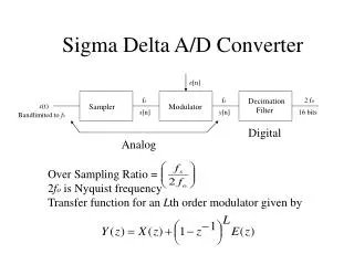
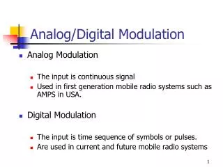
Project Idea Motivation: EE 505 CMOS Data Conversion circuits During the process of digital-to-analog converting • Use Delta-sigma modulator to push noise in music to high frequency band • Use speaker/headphone as the low-pass filter to filtrate high frequency white noise
Top Level Components PCM(digital) In Serial Delta-sigma modulation Pulse Width Modulation (PWM,digital) Signal In Serial Low pass filter
Level-shifter for DVD Output Signal • Output signal(from DVD) voltage: -0.5V~+0.5V Schmidt trigger: SN74LS14N rheostat
Demo • Film1Play CD http://www.youtube.com/watch?v=582E_OXeVOU • Film2Input signal voltage shift http://www.youtube.com/watch?v=uBhcLwn46QM&feature=youtu.be • Film3Sleep mode http://www.youtube.com/watch?v=Q74URMVuhF8&feature=youtu.be
The 3-stage Delta-sigma Modulation • Y1=X+(1-Z-1)•Q • Y2=-Q1+(1-Z-1)•Q2 • Y3=(-Q2)+ (1-Z-1)•Q3 • Y= X+(1-Z-1)3•Q3 PCM PWM
Output: PWM • PWM: digital signal but has analog info.
One Order Noise Shaping Model • Q=Y-U • U-Y=-Q • U=X-Q
One Order Noise Shaping Model • U(n)=X(n)-Q(n-1) • Q(n)=Y(n)-U(n) • Y(n)=X(n)-Q(n-1)+Q(n) =X(n)+Q(n)-Q(n-1) • Q(n)-Q(n-1)=(1-Z-1)•Q • Y=X+(1-Z-1)•Q
The 3-stage Delta-Sigma Modulation • Y1=X+(1-Z-1)•Q • Y2=-Q1+(1-Z-1)•Q2 • Y3=(-Q2)+ (1-Z-1)•Q3 • Y= X+(1-Z-1)3•Q3
Clock Synchronization with DVD • Input signal(from DVD) is in serial: Need to decode SPDIF signal • So need to synchronize clock with DVD
Clock Synchronization • 44.1kHz frame rate×2 channel ×32 data×2 phase =5.6448MHz • Keep detecting : temp1=temp2=temp3 & temp4=temp5=temp6 • Then generate sampling clock @ center pulse
Data Extraction(cont.) • Keep detecting frame header 11100010 or 00011101 | 11100100 or 00011011
Sleep Mode(Power Saving) system
Volume Control • Matlab verification • Lower volume: right shift • Larger volume: left shift • Debounce module( real world)
Reference • http://en.wikipedia.org/wiki/Delta-sigma_modulation • http://www.cscamm.umd.edu/programs/ocq05/adams/adams_ocq05.pdf • http://www.beis.de/Elektronik/DeltaSigma/DeltaSigma.html • http://www.intersil.com/data/an/an9504.pdf • http://hephaestusaudio.com/media/2009/07/MASH-Delta-Sigma.pdf
Thank you! Q and A