Download
1 / 54
550 likes | 699 Vues
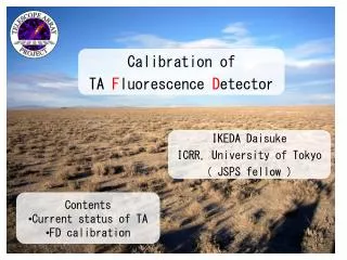
Calibration of TA F luorescence D etector. IKEDA Daisuke ICRR, University of Tokyo ( JSPS fellow ). Contents Current status of TA FD calibration. Telescope Array Collaboration.

E N D
Calibration of TA Fluorescence Detector IKEDA Daisuke ICRR, University of Tokyo ( JSPS fellow ) • Contents • Current status of TA • FD calibration
Telescope Array Collaboration R.U.Abbasi25,T.Abu-Zayyad25,R.Azuma21,J.W.Belz25,D.R.Bergaman19,S.A.Blake25,O.Brusova25,R.Cady25, Z.Cao25,B.G.Cheon6,J.Chiba22,M.Chikawa11,I.S.Cho28,W.R.Cho28,E.J.Cho6,F.Cohen8,K.Doura11, T.Doyle26,T.Fujii17,H.Fujii9,T.Fukuda21,M.Fukushima8,Y.Hayashi17,K.Hayashi21,N.Hayashida8, K.Hibino10,K.Honda27,P.Huenitemeyer13,G.A.Hughes19,D.Ikeda8,N.Inoue20,T.Ishii27,S.Iwamoto27, C.C.H.Jui25,K.Kadota15,F.Kakimoto21,H.S.Kang18,K.Kasahara1,H.Kawai2,S.Kawaka20,S.Kawakami17, E.Kido8,H.B.Kim6,J.H.Kim6,A.Kitsugi8,K.Kobayashi22,Y.Kondo8,Y.Kwon28,J.H.Lim18,K.Martens25, T.Matsuda9,T.Matsuyama17,J.A.J.Matthews24,J.N.Matthews25,M.Mimamino17,K.Miyata22,H.Miyauchi17, M.Mostafa25,T.Nakamura12,S.W.Nam5,T.Nonaka8,S.Ogio17,S.Oh5,M.Ohnishi8,H.Ohoka8,A.Ohshima17, T.Okuda17,J.Ormes23,S.Ozawa1,I.H.Park5,D.Rodriguez25,S.Y.Roh3,D.S,Ryu3,H.Sagawa8,N.Sakurai8, L.M.Scott19,T.Shibata8,H.Shimodaira8,J.D.Smith25,P.Sokolsky25,R.W.Springer25,S.R.Stratton19, G.Sunnis13,S.Suzuki9,M.Takeda8,A.Taketa8,M.Takita8,Y.Tameda21,H.Tanaka17,K.Tanaka7,M.Tanaka9, M.J.Taylor26,M.Teshima14,J.R.Thomas25,S.B.Thomas25,G.B.Thomson19,H.Tokuno8,T.Tomida27,R.Torii8, Y.Tsunesada21,Y.Tsuyuguchi27,Y.Uchihori16,S.Udo1,H.Ukai27,Y.Wada20,V.B.Wickwar26,L.R.Wiencke25, T.D.Wilkerson26,T.Yamakawa8,Y.Yamakawa8,H.Yamaoka9,J.Yang5,S.Yoshida2,H.Yoshii4 (1) Advanced Research Institute for Science and Engineering, Waseda University (2) Chiba University (3) Chungnam National University (4) Ehime University (5) Ewha Womans University (6) Hanyang University (7) Hiroshinma City University (8) Institute for Cosmic Ray Research, University of Tokyo (9) Institute of Particle and Nuclear Studies, KEK (10) Kanagawa University (11) Kinki University (12) Kochi University (13) Los Alamos National Laboratory (14) Max-Planck-Institute for Physics, (15) Musashi Institute of Technology (16) National Institute of Radiological Sciences (17) Osaka City University (18) Pusan National University (19) Rutgers University (20) Saitama University (21) Tokyo Institute of Technology (22) Tokyo University of Science (23) University of Denver (24) University of New Mexico (25) University of Utah (26) Utah State University (27) Yamanashi University (28) Yonsei University (29) Institute for Nuclear Research of Russian Academy of Science ~30 institutes from Japan, USA, Korea, and Russia
Telescope Array Experiment • Desert in Utah ,USA • 3 stations of Fluorescence Detector • 507 Surface Detectors • Full operation was started at Mar/2008 FD (HiRes) ~1400m a.s.l. 31km FD SD
Fluorescence Detector 12telescopes / 1station F.O.V. :3-18°×18° 256PMTs/camera 1021mm 893mm PMT: HAMAMATSU R9508 3300mm F.O.V. :17.7-33°×18° 60mm
FDcurrent status Observation time of BRM (~ 5/Jan/2009) 1417 hours Test Observation (BRM) Observation (LR 6/12 telescope) Full Operation of 3 station
FD -example of event- summation of waveforms
Surface Detector Plastic scintillator (AGASA-type) 3m2, 1.2cm, 2layer Wireless LAN 2.4Ghz 1.2km spacing FADC 12bit 50MHz 120W Solar panel GPS
SD current status Add boundary trigger Live time BR SK SK LR Observation as three divided arrays (504 SD) Full Operation as one large array (507 SD) BR LR
SD monitoring • Every second • # of clock pulse between each 1 PPS from GPS • Time stamp of GPS • # of trigger above 3 MIP. • Every minute • # of trigger above 0.3 MIP • Battery voltage, charge current • Solar panel output voltage • Temperatures of SD equipments • Humidity in the detector box • Every 10 minutes • Histograms of 1MIP & pedestal distributions • Histograms to check PMT linearity • # of satellites used by GPS. Anti-correlation
Characteristics of TA As a hybrid detector • SD • AGASA-type plastic scintillator • Energy can be determined as independent of FD • FD • HiRes-1 was moved as one of the TA FD station. • Absolute calibration by using Electron beam accelerator (TA-LINAC) • The disagreement of AGASA and HiRes can be tested directly. • Fine energy measurement as direct determination by SD, FD with TA-LINAC, and comparison in hybrid event.
Main items of FDCalibration • Telescope • Absolute gain (photon-to-FADC) measurement by CRAYS • Relative gain monitor by Xe and YAP • On-site uniformity scanner • Mirror reflectance measurement • Atmospheric • LIDAR • Cloud monitor • End-to-end • CLF • TA-LINAC The preparation of 1st data set of FD calibration for telescope is almost finished.
PMT Calibration - absolute gain- Peak: 0.5075 count/photon(337.1nm) CRAYS • Absolute PMT gain measurement Using N2 laser Rayleigh scattering in N2 gas. • The absolute gain (photon-to-FADC) of 2 or 3 PMTs in one camera are measured and adjusted by CRAYS. ~1% N2 Laser
PMT Calibration –relative gain- YAP pulser YAP pulsers are installed on the standard PMTs calibrated by CRAYS. 2 or 3 PMTs with YAP are installed in each camera. YAP is stable light source for gain monitoring. YAP (YAlO3:Ce+241Am) Peak 365nm 50Hz~100Hz Xe flusher Result of gain adjustment After adjustment All HV is 850V The gain adjustment and relative gain monitoring is done by Xe flusher. This measurement is done every 1 hour on observation time. ~1%
PMT Calibration-temperature characteristics of PMT and YAP- Incubator(-10~40degree) Stable room temp. (T±0.5℃) YAP PMT Optical fibers #5 #1 Function gen. #4 UV-LED #3 Splitter #0 #2 Dark box Patch panel Signal Digitizer/Finder
Temperature Coefficientsof PMTs with pre-amplifier %/℃ %/℃ %/℃ %/℃ %/℃ %/℃ %/℃ %/℃ -0.4 -0.4 -0.4 -0.4 -0.4 -0.4 -0.4 -0.4 #2 #3 #4 #5 -0.5 -0.5 -0.5 -0.5 -0.5 -0.5 -0.5 -0.5 -0.6 -0.6 -0.6 -0.6 -0.6 -0.6 -0.6 -0.6 -0.7 -0.7 -0.7 -0.7 -0.7 -0.7 -0.7 -0.7 -0.8 -0.8 -0.8 -0.8 -0.8 -0.8 -0.8 -0.8 Average ~ -0.65 %/deg -10 0 1020 30 [℃] -10 0 1020 30 [℃] -10 0 1020 30 -10 0 1020 30 [℃] -10 0 1020 30 [℃] -10 0 1020 30 [℃] -10 0 1020 30 [℃] -10 0 1020 30 #6 #7 #8 #9 TA ALL meeting
Temperature Coefficients of YAP %/℃ %/℃ %/℃ %/℃ %/℃ %/℃ %/℃ %/℃ +0.2 +0.2 +0.2 +0.2 +0.2 +0.2 +0.2 +0.2 #2 #3 #4 #5 0 0 0 0 0 0 0 0 -0.2 -0.2 -0.2 -0.2 -0.2 -0.2 -0.2 -0.2 -0.4 -0.4 -0.4 -0.4 -0.4 -0.4 -0.4 -0.4 -0.6 -0.6 -0.6 -0.4 -0.6 -0.6 -0.6 -0.6 ~ -0.2 %/deg -10 0 1020 30 [℃] -10 0 1020 30 [℃] -10 0 1020 30 -10 0 1020 30 [℃] -10 0 1020 30 [℃] -10 0 1020 30 [℃] -10 0 1020 30 [℃] -10 0 1020 30 #6 #7 #8 #9
Other items (filters,QE,CE,uniformity) XY-Scanner Paraglas transparency HITACHI U-1100 Spectrophotometer paraglas PMT BG3 BG3 transparency PMT uniformity Q.E. (HAMMATSU) C.E. (HAMAMATSU) 0.909 +0.005 -0.020
PMTuniformity (XY Scanner) • XY Scanner • 8LED • Spot: 4mm • Step: 4mm • We create typical uniformity by using 253PMTs (256 – 3 with YAP). • Because of position and direction of each LED is difference, we can obtain the fine uniformity map better than the resolution of XY Scanner. We get the uniformity map of 1mm×1mm resolution. • Comparison with HAMAMATSU measurement • → Consistent!
Mirror reflectance KONICA MINOLTA CM-2500d • In most dirty term, reflectance is affected by • Lower telescope:~-10% • Upper telescope:~-5% • But each reflectance was almost recovered by mirror washing Measurement point e.g.) BRM,camera10,mirror3 (most dirty mirror) Mirror washing→
Atmospheric - LIDAR and cloud monitor - LIDAR LASER: 5mJ,355nm 30cm telescope LIDAR is operated every start & end time of observation The 14 pictures is taken every 1 hour. 12 picture is corresponded the F.O.V. of each 12 telescope. IR Camera
Central Laser Facility Central Laser Facility (CLF) Steerable Nd:YAG laser 355 nm, 5 mJ Shooting every 1 hour. Atmospheric monitoring, “Test beam” Black Rock Mesa June 13, 2007, 05:45 (UTC) Long Ridge Peak time diff. < 100ns frame head (sec)= 01.0000630 frame head = 01.0000630
TA-LINAC • Linacの絵
Air shower Linac Beam FD Absolute energy calibration! 100m 10km TA-LINAC –motivation- • Uncertainties of FD (design report of TA) • Fluorescence yield 15% • Transparency of Air 11% • Telescope Calibration 10% • Reconstruction 6% More than 20% We can get integrated calibration constant except for air. End-to-end calibration! (We can connect energy deposit to FADC count directly.)
:F.O.V.(upper camera) :F.O.V.(lower camera) vertical FD Linac horizontal 100m TA-LINAC -Basic specs- • Specs of TA-LINAC • Particle:e- • Energy:10, 20, 30, 40 MeV • (variable) • Pulse width:1μsec • Peak current:0.16mA • (109e-(=160pC)/pulse) • Frequency:~1Hz • Distance from FD:100m @KEK Construction : finished Beam test : finished (08/Feb/22 – 08/Dec/10 716hours) Simulated by geant4 (40MeV)
TA-LINAC –Result of beam test- Waveforms Beam Current Measurements EGUN Mon1 : Faraday Cup (absolute) Mon2 : Core Monitor (relative) RF Reference value = 160pC Output beam Beam Charge w/ Faraday Cup( pC/pulse/q) Beam Energy Spectrum + Data set#1( ‘08 Nov.11th ) + Data set#2( ‘08 Nov.12th ) + Data set#3( ‘08 Nov.20th ) + Data set#4( ‘08 Nov.21th ) + Data set#5( ‘08 Nov.25th ) ● Data Set 1 ● Data Set 2 ● Data Set 3 Peak=39.7MeV Spread < 1% Core Monitor Output (mV×μs/pulse ) Diff. btw each Data : less than 5%
TA-LINAC –Current Status- Feb/06 @KEK • Beam Test @KEK • Beam test was finished at Dec/10. • Transport to Utah from KEK • Preparation for carrying : almost finished. • Shipping from YOKOHAMA : Mar/1(?) • TALinac will be arrived at Utah on end of Mar • Shooting at Utah • We can start shooting at next Apr-May !!.
Conclusion • FD Calibration • The 1st data set of telescope calibration was almost prepared. • TA-LINAC calibration will be started at next Apr-May. • TA • TA will present the first result at ICRC09 with data equivalent of about 1 AGASA. • Linacの絵 Grazie mille
TA-LINAC –for fluorescence yield measurement- • TA-FD can be calibrated end-to-end by TA-LINAC • The difference btw LINAC beam and Air shower • The height of the emission the photon • Air shower (XMAX) ~ a few km • LINAC beam ~70m • Atmospheric condition • Pressure, temperature has systematic difference. • The variation of humidity is bigger than high atmosphere. • (affected by the rain of before days. • Our countermeasure • Use result of yield measurement • Use the result of only dry days. • Of cause, we can measure this dependence by using daily difference of atmospheric condition.
Mirror reflectance 1 KONICA MINOLTA CM-2500d (360~740nm,10nm pitch) 1, The measured data is consistent with maker data except for short wavelength. • 2, In this variation of reflectance, We can see • Height dependence • No wavelength dependence • So we use • Maker data • spectrum • Absolute reflectance at installation. • Measured data by CM-2500d • Relative variation of reflectance 2008/06(before washing) LR upper telescope Variation from installation
Mirror reflectance 2 • We prepared data mirror by mirror. • 250nm-740nm • Mean ± standard deviation. • 1nm supplement with natural cubic spline. • 10 days supplement with linear approximation. • In most dirty term, reflectance is affected by • Lower telescope:~-10% • Upper telescope:~-5% • But each reflectance was almost recovered by mirror washing Measurement point e.g.) BRM,camera10,mirror3 (most dirty mirror) Mirror washing→
PMTuniformity (XY Scanner) • XY Scanner • Spot: 4mm • Step: 4mm • 8LED • Method of analysis • We adjust position of each PMTs by center of gravity. • After normalization, we add data of each PMTs. (intensity of each LEDs) • This data is normalized by “The average value of each bins inside circle (dia. 36mm) will be 1”. This condition is determined by CRAYS. Comparison with HAMAMATSU measurement → Consistent !
XY Scanner PMT境界 • PMTごとの中心距離は62mm • 全体の積分値に対する境界の外のBinの積分値の割合は • 境界線の外のBin→0.1% • 境界線上のBin→0.9% PMT境界
Uniformity:ratio of deviation in each bins • Evaluation of characteristics of each PMTs. • sigma/mean ratio plot. • Peak value is about 4%. High sensitivity area has this value. • The edge area (low sensitivity) has bigger error ratio. • Inside 90% circle area (dia. 27.5mm), maximum value is 33%, and 95% is less than 10%.
反射率の時間変化による系統誤差の見積もり 時間変化の絵の描き方 ①, 全データ使用 ②, 2007/11は一個前の測定データを使用 BRM camera4 赤:① 青:② 全ての鏡ごとに①と②を比較し、差が最大となる値を求める。
反射率の時間変化による系統誤差の見積もり2反射率の時間変化による系統誤差の見積もり2 • BRM,LRの全432枚の鏡についてのデータ。 • 全データ使用の場合を測定結果とし、2007/11の補正を入れた場合に対してどの程度反射率が減少するのかを見積もった。 • ピークは~-2%、最大で-7%程度 • 通常のイベントに対する影響をさっくり見積もる。 • 通常のイベントによる光スポットは、18枚の鏡を大体均等に使っていると仮定。 • →18枚の平均値が影響 • 下のカメラで最大-3.5%、上のカメラで最大-2%程度。 • 正確な値はシミュレーションで。
反射率の分布 • それぞれ6点しか測定していないので分布が分からない。 • 各列毎の鏡測定データを集めて、分布を見る。 • 2008/06,LR,上下のカメラ • 下の図は360nmの物 • まぁまぁガウス分布で合っている。→とりあえずガウス分布 • それぞれの測定値は平均値、標準誤差、標準誤差/(測定点数)^0.5の3つとする。
:F.O.V.(upper camera) :F.O.V.(lower camera) vertical FD Linac horizontal 100m TA-Linac -Basic specs- • Specs of TA-Linac • Particle:e- • Energy:10, 20, 30, 40 MeV • (variable) • Pulse width:1μsec • Peak current:0.16mA • (109e-(=160pC)/pulse) • Frequency:1Hz • Distance from FD:100m 40MeV×109e- @100m → ~1016eV ⇔1020 eV @10km We have to prepare power generator and cooling water by ourselves. We install this systems in two containers.(movable?) Simulated by geant4 (40MeV)
Mirror calibration Curvature radius Spot size at curvature radius measured by TAMED Light source Image scanner mirror Number of mirrors Number of mirrors TAMED Curvature radius [mm] Spot size @ curvature radius [mm] Reflectance (λ dependence) measured by Spectrophotometer (Konica-Minolta CM-2500d) 360nm~740nm 90 Reflectance [%] 85 420 360 Wavelength [mm]
6067mm LED Laser (center axis) Spot Mirror alignment All mirrors were adjusted using BANANA-3 BANANA-3 LED Spot ~20mm
Current 1mip gain distribution E. Kido gain distribution(detector): 45±5 count At under 4*10^6 gain 1mip peak are around 70, (some PMT is more higher).
Maximum Number of particle Hit in 20 nsec time bin as function of distance from core Typ 570m Typ: at up to 570 m from core TA can measure with less non-linearity than 5%.
Slide : by M. Chikawa (2007) TA IR camera
IR data taking sequence • Once per 50min (3000 sec) • 14 pictures in a sequence • 12 directions : 6 lower (12 deg) and 6 upper (30 deg) • Vertical, horizontal • Sometimes there are missing pictures of some directions • (Instructions (PC -> camera) did not received correctly) • By analyzing PC logs and time stamps of the IR data, missing parts identified. 13 14 (vertical) (horizontal) 7 8 9 10 11 12 6 5 4 3 1 2
Statistics 2007/Dec/29 - 2009/Jan/04