Full Mission Simulation Report
Full Mission Simulation Report. University of Minnesota Alexander Richman Jacob Schultz Justine Topel Will Thorson 4/23/2012. Mission Overview. Our mission is to demonstrate the feasibility of using active noise cancellation on board a rocket for future experiments. . Mission Overview.

Full Mission Simulation Report
E N D
Presentation Transcript
Full Mission Simulation Report University of Minnesota Alexander Richman Jacob Schultz Justine Topel Will Thorson 4/23/2012
Mission Overview • Our mission is to demonstrate the feasibility of using active noise cancellation on board a rocket for future experiments.
Mission Overview • Our mission is to demonstrate the feasibility of using active noise cancellation on board a rocket for future experiments. • We tested the impact g force on the structure without the onboard electronics because we still needed to complete a couple of the mounts and had to send the payload in to the shop to be modified. • The shop required the payload right away if we were to be able to get everything completed as soon as possible
Mechanical/Structure • The structure was slightly too large in diameter to fit in the canister. It has been taken back to the shop to be fitted properly. • We also had to mill some holes in the canisters for running wires to connect all of the electronics throughout the payload. • The integration procedure is a bottom up approach. The assembly starts with the bottom plate and build on top of it.
Mechanical/Structure cont. • We have a parts list and understand there will not be a machine shop at Wallops • Our ballast for ensuring we have proper weight is weighted tape which can be found in golf stores. • The exact weight of the payload will be determined when we get it back from the shop with the modifications.
Mechanical/Structure cont. • We tested the impact g force on the structure without the onboard electronics because we still needed to complete a couple of the mounts and had to send the payload in to the shop to be modified. • The shop required the payload right away if we were to be able to get everything completed as soon as possible
Mechanical/Structure • For the test readiness review we have to test the vibrational durability of the electronics and their new mounts in the structure. • We also have to get the final weight and properly ballast it.
Electrical/CDH Standoff Standoff Design overview: We have two identical chambers. The power supply, consisting of the battery and regulating circuit supplies power to both mics, the ANC system, the data logger and our filters. The mic signal is passed through the active filter/preamps and into the data logger. Mic 1 Mic 2 ANC System Dummy System Battery Filters Data logger Power
Power Supply Subsystem Overview • We will be using the power supply that was flown last year. The power supply is in working condition and, with the new batteries we ordered, will be ready for flight.
Power (EPS) • Power supply has been tested • Tests conducted • 1 hour • See if it powers everything • Does is power everything? Yes -> Success • When NASA connects the activation switch (Winchester switch), all subsystems will activate.
Power (EPS) • We had two new battery packs made. • We have done testing recently using a plug-in power supply. • We have to add a voltage divider/regulator to our development board for powering the microphones and ANC system.
Data Logger Subsystem Overview • We will be using the data logger that was flown last year. The data logger works, but we are adding low pass filters and a microphone preamp on the input side.
Electrical/CDH • The data collection system is working and we are getting data that is sensible from running tests. • Tests conducted • Short Duration: 1-5 seconds • To see if there is a difference between the noise power between experimental and control methods • Power spectral analysis was used to determine success • We have seen a 3dB reduction in noise at this point (more on this later) • Integration is still taking place. We are working on combining all of the things and don’t foresee any issues.
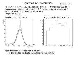
Filtered Test Results • The following graph shows the decibel level of attenuation from our ANC tests. • Data processed by bandpass filtering the control and test spectrum in 100 Hz increments, breaking down how effective the attenuation is by frequency. • Midpoints plotted, ex: 300-400Hz band is marked by 350 Hz on the plot
ANC Filtered Test Results The graph to the left shows a reduction in noise as measured in dB. This is a good result and shows that the system is working. We hope that it will be even better after adding the filter/preamp.
Audio Spectrum Results – Test(Red) Control(Blue) The fft shows a clear reduction in noise using the ANC system. The blue is the control case.
Test Summary • Everything worked as planned. • All electronics communicated • The data logger saw the audio signal • Reasonable data was seen • Sensors may need some calibration for robustness, although it is not essential
Action Item Summary • In the next week we are expecting to get shipments in with the parts for the filters and run tests with them and the data logger making sure everything interfaces correctly • By the week after we expect to have the payload with all of the mounts and able to properly fit in the canister. We will put everything together and perform vibrational testing with a sub woofer.
Pictures Payload structure
Pictures cont. Microphone and speaker Data logger Power supply
Conclusions • We are finishing work on fixing all of the issues which popped up during full system integration and mission testing. • We have some work to do but we still believe we will be ready to fly by launch.
Appendix • Extra/additional data plots • Additional data not immediately relevant to presentation