Download
1 / 17
170 likes | 300 Vues
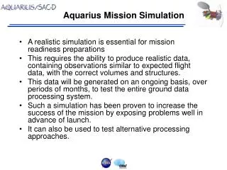
This report outlines progress on a mission simulation conducted by the New Jersey Space Grant Consortium in collaboration with Stevens Institute of Technology and Rutgers University. The mission aims to gather and analyze data for future space research through a payload designed for various experiments. The report covers assembly testing, mechanical structures, electrical integration, fluid management, and software operations. Key action items, current subsystem status, and data sampling efforts are highlighted.

E N D
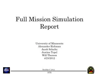
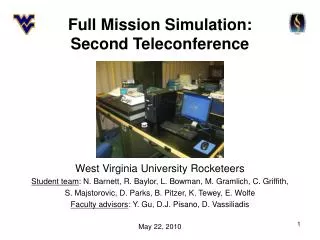
Full Mission Simulation Report New Jersey Space Grant Consortium at Stevens Institute of Technology and Rutgers University Ethan Hayon, Mark Siembab, Mike Giglia, Robert Hopkins, Sean Watts
Mission Statement: –To collect and analyze data for future space research operations through various experiments designed and implemented on a payload.
Mission Overview: • The payload has been assembled and we have began testing it. • Pressure tests of the ACV and pneumatic components will take place in the upcoming week. • The IR temperature sensor will be mounted in the coming week. • We are working on acquiring access to a vibration table. • Code will be organized into cleaner functions for easier maintainability.
Subsystem Overview: • Mechanical/Structure • Electrical • Power / EPS • Atmospheric Containment Vessel/Pneumatics • Software
Mechanical / Structure: • After minor adjustments to the pneumatic system, nearly all components were integrated successfully. • Written integration procedure and current parts list have not been drafted but will be, if required; so far we have encountered no problems with assembly, nor keeping track of components. • Spare hardware and components are available for nearly every subsystem. • Payload weight: 1318.4g (46.5 ounces or 2.9 lbs) • A ballast may be necessary; it will consist of nuts + short bolts (steel) mounted through the payload plates at specific locations.
Mechanical / Structure: • Integrating with Mitchell County College: • Aluminum hex standoffs will be used to combine the payloads. • Inside will be threaded steel rods used to connect the female-female aluminum standoffs. • These standoffs are 2" in height each making our payload height 4.5" including the thickness of the plates. • The combined center of gravity is to be reviewed this week to be finalized. • Action Items: Teleconference with Mitchell County College regarding final integration plans and combined mass and center of gravity.
Electrical: • All electronics have been integrated except for the Infrared Temperature Sensor. The sensor is connected, but not yet attached to the plate. • We are unsure of the best location to mount it. It needs to be as close to the rocket skin as possible. • Can we use the access window on the canister? • We have received data, and it makes sense. • Data on the next slide • Once we connect the IR temp sensor (code is already written and functional) the payload will be electrically complete. • We also need to organize the wires and stake down the components.
Sample Data (From SD Card): Time: 20 | x: 0 | y: 0 | z: 7 | CO2: 805 Time: 21 | x: 0 | y: 1 | z: 8 | CO2: -1 Time: 22 | x: 0 | y: 0 | z: 8 | CO2: -1 Time: 23 | x: 0 | y: 0 | z: 7 | CO2: -1 Time: 24 | x: 0 | y: 0 | z: 7 | CO2: -1 Time: 25 | x: 0 | y: 1 | z: 7 | CO2: -1 Time: 26 | x: 0 | y: 1 | z: 7 | CO2: -1 Time: 27 | x: 1 | y: 0 | z: 7 | CO2: -1 Time: 28 | x: 0 | y: 0 | z: 7 | CO2: -1 Time: 29 | x: 2 | y: 0 | z: 12 | CO2: -1 Time: 30 | x: 0 | y: 0 | z: 7 | CO2: 1255 Time: 31 | x: 0 | y: 0 | z: 7 | CO2: -1 Time: 32 | x: 0 | y: 0 | z: 7 | CO2: -1 Time: 33 | x: 0 | y: 0 | z: 7 | CO2: -1 Time: 34 | x: 0 | y: 0 | z: 7 | CO2: -1 Time: 35 | x: 0 | y: 0 | z: 9 | CO2: -1 Time: 36 | x: 0 | y: 0 | z: 7 | CO2: -1 Time: 37 | x: 0 | y: 0 | z: 6 | CO2: -1 Time: 38 | x: 0 | y: 0 | z: 3 | CO2: -1 Time: 39 | x: 0 | y: 3 | z: 2 | CO2: -1 Time: 40 | x: 0 | y: 0 | z: 8 | CO2: 1285 Each increment to "time" is 1/20th of a second.
Power / EPS: • The 600mAh NiCD battery used for initial testing lasted approximately 45 minutes • The idle current draw of the servo proved more significant than expected, but still marginal compared to the previous pinch valve and will not cause any problems • Acquisition of a higher capacity 9.6V NiMH battery pack. • Ordered on April 28th
Atmospheric Containment Vessel / ACV: • Final machining on the ACV was completed and it was mounted successfully. • ACV ports were over-tapped and angled barbed fittings were used to minimize the ACV's footprint and simplify assembly. • Silicone-bead sealing will be pressure tested within the next week.
Pneumatic System: • A welded metal bracket was devised to secure the ball valve to the plate. • Bracket provides 1/2" of left-right position adjustment if required. • HS-625MG Servo tested and found to actuate ball valve with no problems. • Servo mounted to ball-valve using machined metal parts to ensure durability.
Software: • The software ran as expected. • We are still working out the timing for when the inlet valve will open and close. • Data was written successfully to the SD Card. • We are sampling the IR temperature sensor and the accelerometer at 20Hz. The CO2 sensor is being sampled at 2Hz (using a mod 10 operation) • Set up the timing on the open/close valve operation. Right now we can automatically open and close the valve, however, it is not on a timer.
Action Item Summary: • Order a third revision of the shield. This board will contain some extra ports for flexibility if we choose to add components. Also, additional power outputs will be helpful. • Order before May 1st. • Use a higher capacity NiMH battery • Ordered on April 29th. • Set timing on ball valve open/close action • Coded before May 1st
Conclusions: • Currently we do not have a location planned for our IR thermometer and we request advice as it is expected to measure rocket skin temperature. Note: C of G will not be impacted by placement of thermometer because it weighs <1 gram.