Download
1 / 67
670 likes | 800 Vues
This document explores the intricacies of measuring light in 3D scenes, focusing on illumination, shape, movement, and surface properties. It covers essential concepts such as irradiance, flux, radiance, and the Bidirectional Reflectance Distribution Function (BRDF). Key topics include the interaction of light with surfaces, light measurement techniques, and the mathematical foundations behind them. The document also presents resources for interactive learning and demonstration of optical concepts, providing comprehensive insights for students and professionals interested in computer graphics and light simulation.

E N D
CS 395/495-25: Spring 2004 IBMR: Measuring Lights, Materials, Lenses and more Jack Tumblin jet@cs.northwestern.edu
Recall: An Image Is… Light + 3D Scene: Illumination, shape, movement, surface BRDF,… 2D Image: A map of light intensities A ‘Camera’: ?What are ALL the possibilities? Position(x,y)
An Planar Projection Image Is… Light + 3D Scene: Illumination, shape, movement, surface BRDF,… 2D Image: Collection of rays through a point Image Plane I(x,y) Position(x,y) Angle(,) ‘Center of Projection’ (P3 or P2 Origin)
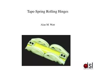
Image Making: Pinhole Thin Lens • Interactive Thin Lens Demo (search ‘physlet optical bench’) http://www.swgc.mun.ca/physics/physlets/opticalbench.html • From this geometry (for next time) Can you derive Thin Lens Law?
Incident Light Measurement • Flux W = power, Watts, # photons/sec • Uniform, point-source light: flux on a patch of surface falls with distance2 E = Watts/r2 r
Light Measurement • Flux W = power, Watts, # photons/sec • Irradiance E: flux arriving per unit area,(regardless of direction) E = Watts/area = dW/dA But direction makes a big difference when computing E...
Foreshortening Effect: cos() • Larger Incident angle ispreads same flux over larger area • flux per unit area becomes W cos( i) / area • Foreshortening geometry imposes an angular term cos(i) on energy transfer circular ‘bundle’ of incident rays, flux W W i
Irradiance E • To find irradiance at a point on a surface, • Find flux from each (point?) light source, • Weight flux by its direction: cos(i) • Add all light sources: or more precisely, integrate over entire hemisphere Defines Radiance L: L = (watts / area) / sr (sr = steradians; solid angle; = surface area on unit sphere)
Radiance L • But for distributed (non-point) light sources? integrate flux over the entire hemisphere . But what are the units of what we integrate? Radiance L L = (watts / area) / sr (sr = steradians; solid angle; = surface area on unit sphere)
Lighting Invariants Cam Why doesn’t surface intensity change with distance? • We know point source flux drops with distance: 1/r2 • We know surface is made of infinitesimal point sources... ‘intensity’: 1/r2 ‘intensity’: constant (?!?!)
Lighting Invariants Cam Why doesn’t surface intensity change with distance? Because camera pixels measure Radiance, not flux! • pixel value flux *cos() / sr • ‘good lens’ design: cos() term vanishes. Vignetting=residual error. • Pixel’s size in sr fixed: • Point source fits in one pixel: 1/r2 • Viewed surface area grows by r2, cancels 1/r2 flux falloff Light ‘intensity’: 1/r2 Surface ‘intensity’: constant (?!?!)
Lighting Invariants Radiance Images are LINEAR: ·(Radiance caused by (Light 1)) + ·(Radiance caused by (Light 2)) = Radiance caused by (· Light 1 +·Light 2) = + http://www.sgi.com/grafica/synth/index.html
Lighting Invariants Light is Linear: ·(Radiance caused by (Light 1)) + ·(Radiance caused by (Light 2)) = Radiance caused by (· Light 1 +·Light 2) Allows ‘negative’ light! = - http://www.sgi.com/grafica/synth/index.html
Point-wise Light Reflection • Given: • Infinitesimal surface patch dA, • illuminated by irradiance amount E • from just one direction (i,i) • How should we measure the returned light? • Ans: by emittedRADIANCEmeasured for alloutgoing directions:(measured on surface of ) i dA i
Point-wise Light Reflection: BRDF Le i Ei dA i Bidirectional Reflectance Distribution Function Fr(i,I,e,e) = Le(e,e) / Ei(i,i) • Still a ratio (outgoing/incoming) light, but • BRDF: Ratio of outgoing RADIANCE in one direction: Le(e,e)that results from incoming IRRADIANCE in one direction: Ei(i,i) • Units are tricky:BRDF = Fr = Le /Ei
Point-wise Light Reflection: BRDF Le i Ei dA i Bidirectional Reflectance Distribution Function Fr(i,I,e,e) = Le(e,e) / Ei(i,i) • Still a ratio (outgoing/incoming) light, but • BRDF: Ratio of outgoing RADIANCE in one direction: Le(e,e)that results from incoming IRRADIANCE in one direction: Ei(i,i) • Units are tricky:BRDF = Fr = Le /Ei = ( Watts/area/sr) /(Watts/area)
Point-wise Light Reflection: BRDF Bidirectional Reflectance Distribution Function Fr(i,I,e,e) = Le(e,e) / Ei(i,i) • Still a ratio (outgoing/incoming) light, but • BRDF: Ratio of outgoing RADIANCE in one direction: Le(e,e)that results from incoming IRRADIANCE in one direction: Ei(i,i) • Units are tricky:BRDF = Fr = Le /Ei = ( Watts/area/sr) / = 1/sr (Watts/area)
Point-wise Light Reflection: BRDF Le i Ei dA i Bidirectional Reflectance Distribution Function Fr(i,I,e,e) = Le(e,e) / Ei(i,i), and (1/sr)units • ‘Bidirectional’ because value is SAME if we swap in,out directions: (e,e) (i,i) Important Property! aka ‘Helmholtz Reciprocity’ • BRDF Results from surface’smicroscopic structure... • Still only an approximation: ignores subsurface scattering...
Scattering Difficulties: Le i Ei dA i For many surfaces, single-point BRDFs do not exist Example: Leaf Structure Angles Depend on refractive index, scattering, cell wall structures, etc. Depends on total area of cell wall interfaces
Subsurface Scattering Models Classical: Kubelka-Monk(1930s, for paint; many proprietary variants), CG approach: Hanrahan & Krueger(1990s) More Recent: ‘dipole model’ (2001, Jensen) Marble BRDF Marble BSSRDF
Subsurface Scattering Models Classical: Kubelka-Monk(1930s, for paint; many proprietary variants), CG approach: Hanrahan & Krueger(1990s) More Recent: ‘dipole model’ (2001, Jensen) Skin BRDF (measured) Skin BSSRDF (approximated)
BSSRDF Model Approximates scattering result as embedded point sources below a BRDF surface: BSSRDF: “A Practical Model for Subsurface Light Transport” Henrik Wann Jensen, Steve Marschner, Marc Levoy, Pat Hanrahan, SIGGRAPH’01 (online)
BSSRDF Model • Embedded point sources below a BRDF surface • Ray-based, tested, Physically-Measurable Model • ?Useful as a predictive model for IBMR data? Wann Jensen et al., 2001
Summary: Light Measurement • Flux W = power, Watts, # photons/sec • Irradiance E = Watts/area = dW/dA • Radiance L = (Watts/area)/sr = (dW/dA)/sr • BRDF: Measure EMITTED radiance that results from INCOMING irradiance from just one direction:BRDF = Fr = Le / Ei = (Watts/area) / (Watts/areasr)
IBMR Tools • Digital Light Input: • Light meter: measure visible irradiance E (some have plastic ‘dome’ to ensure accurate foreshortening) • Camera: pixels measure Radiance Li ; flux arriving at lens from one (narrow solid) angle • Digital Light Output: • Luminaires: point lights, extended(area) sources • Emissive Surfaces: CRT, LCD surface • Projectors: laser dot,stripe,scan; video display • Light Modifiers (Digital?): • Calibration objects, shadow sources, etc. • Lenses,diffusers, filters, reflectors, collimators... • ?Where are the BRDF displays / printers?
Two Big Missing Pieces • Computer controlled BRDF. • Can we really do without it? • are cameras and projectors enough to ‘import the visible world’ into our computers? • BRDF is not enough: • Subsurface scattering is crucial aspect of photographed images • ? how can we model it? measure it? use it?
More help: • GREAT explanation of BRDF: • www.cs.huji.ac.il/~danix/advanced/RenderingEq.pdf • Some questions about measuring light:
IBMR---May 13,2004: Projects? (due Tues May 25!) Let’s discuss them…
Summary: Light Measurement • Flux W = power, Watts, # photons/sec • Irradiance E = Watts/area = dW/dA • Radiance L = (Watts/area)/sr = (dW/dA)/sr • BRDF: Measure EMITTED radiance that results from INCOMING irradiance from just one direction:BRDF = Fr = Le / Ei = (Watts/area) / (Watts/areasr)
IBMR: Measure,Create, Modify Light How can we measure ‘rays’ of light? Light Sources? Scattered rays? etc. Cameras capture subset of these rays. Shape, Position, Movement, Emitted Light Reflected, Scattered, Light … BRDF, Texture, Scattering Digital light sources (Projectors) can produce a subset of these rays.
‘Scene’ modifies Set of Light Rays What measures light rays in, out of scene?
Measure Light LEAVING a Scene? Towards a camera?...
Measure Light LEAVING a Scene? Towards a camera: Radiance. Light Field Images measure RadianceL(x,y)
Measure light ENTERING a Scene? from a (collection of) point sources at infinity?
Measure light ENTERING a Scene? from a (collection of) point sources at infinity? ‘Light Map’ Images (texture map light source) describes IrradianceE(x,y)
Measure light ENTERING a Scene? leaving a video projector lens? ‘Reversed’ Camera: emits RadianceL(x,y) RadianceL
Measure light ENTERING a Scene? from a video projector?—Leaving Lens: RadianceL IrradianceE
‘Full 8-D Light Field’ (10-D, actually: time, ) • Cleaner Formulation: • Orthographic camera, • positioned on sphere around object/scene • Orthographic projector, • positioned on spherearound object/scene • (and wavelength and time) F(xc,yc,c,c,xl,yl l,l, , t) camera projector
Summary: Light Measurement • Flux W = power, Watts, # photons/sec • Irradiance E = Watts/area = dW/dA • Radiance L = (Watts/area)/sr = (dW/dA)/sr • BRDF: Measure EMITTED radiance that results from INCOMING irradiance from just one direction:BRDF = Fr = Le / Ei = (Watts/area) / (Watts/areasr) Lenses map radiance to the image plane (x,y): THUS: Pixel x,y must measureRadiance L at x,y. well, not exactly; there are distortions!…
What do Photos Measure? What We Want What We Get
Film Response:(digital cameras, video cards too!)approximately linear, but ONLY on log-log axes.
Two Key parameters: m == scale == exposure == gamma == ‘contrastyness’
Problem:Map Scene to Display Domain of Human Vision: from ~10-6 to ~10+8 cd/m2 starlight moonlight office light daylight flashbulb 10-6 10-2 1 10 100 10+4 10+8 ?? ?? 0 255 Range of Typical Displays: from ~1 to ~100 cd/m2
High-Contrast Image Capture? • An open problem! (esp. for video...) • Direct (expensive) solution: • Flying Spot Radiometer: brute force instrument, costly, slow, delicate • Novel Image Sensors: line-scan cameras, logarithmic CMOS circuits, cooled detectors, rate-based detectors... • Most widely used idea: multiple exposures • Elegant paper (Debevec1996) describes how: (On class website)
starlight moonlight office light daylight flashbulb Use Overlapped Exposure Values
starlight moonlight office light daylight flashbulb Use Overlapped Exposure Values