Lecture 23
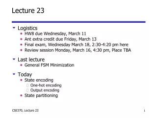
Lecture 23. Logistics HW8 due Wednesday, March 11 Ant extra credit due Friday, March 13 Final exam, Wednesday March 18, 2:30-4:20 pm here Review session Monday, March 16, 4:30 pm, Place TBA Last lecture General FSM Minimization Today State encoding One-hot encoding Output encoding

Lecture 23
E N D
Presentation Transcript
Lecture 23 • Logistics • HW8 due Wednesday, March 11 • Ant extra credit due Friday, March 13 • Final exam, Wednesday March 18, 2:30-4:20 pm here • Review session Monday, March 16, 4:30 pm, Place TBA • Last lecture • General FSM Minimization • Today • State encoding • One-hot encoding • Output encoding • State partitioning
FSM design • FSM-design procedure • State diagram • state-transition table 3. State minimization 4. State encoding 5. Next-state logic minimization 6. Implement the design
Usual example: A vending machine 15 cents for a cup of coffee Doesn’t take pennies or quarters Doesn’t provide any change Reset N VendingMachineFSM Open CoinSensor ReleaseMechanism D Clock
present inputs next outputstate D N state open 0¢ 0 0 0¢ 0 0 1 5¢ 0 1 0 10¢ 0 1 1 – – 5¢ 0 0 5¢ 0 0 1 10¢ 0 1 0 15¢ 0 1 1 – –10¢ 0 0 10¢ 0 0 1 15¢ 0 1 0 15¢ 0 1 1 – –15¢ – – 15¢ 1 Reset 0¢ N 5¢ D D' N' N 10¢ D 1 N + D 15¢ [open] symbolic state table A vending machine: After state minimization D' N' D' N'
present state inputs next state output Q1 Q0 D N D1 D0 open 0 0 0 0 0 0 0 0 1 0 1 0 1 0 1 0 0 1 1 – – – 0 1 0 0 0 1 0 0 1 1 0 0 1 0 1 1 0 1 1 – – – 1 0 0 0 1 0 0 0 1 1 1 0 1 0 1 1 0 1 1 – – – 1 1 – – 1 1 1 A vending machine: State encoding
A vending machine: Logic minimization Q1 Q1 Q1 D0 Open D1 0 0 1 1 0 1 1 1 X X X X 1 1 1 1 0 1 1 0 1 0 1 1 X X X X 0 1 1 1 0 0 1 0 0 0 1 0 X X 1 X 0 0 1 0 N N N D D D Q0 Q0 Q0 D1 = Q1 + D + Q0 N D0 = Q0’ N + Q0 N’ + Q1 N + Q1 D OPEN = Q1 Q0
State encoding • Assume n state bits and m states • 2n! / (2n – m)! possible encodings • Example: 3 state bits, 4 states, 1680 possible state assignments • Want to pick state encoding strategy that results in optimizing your criteria • FSM size (amount of logic and number of FFs) • FSM speed (depth of logic and fan-in/fan-out) • FSM ease of design or debugging
State-encoding strategies • No guarantee of optimality • An intractable problem • Most common strategies • Binary (sequential) – number states as in the state table • Random – computer tries random encodings • Heuristic – rules of thumb that seem to work well • e.g. Gray-code – try to give adjacent states (states with an arc between them) codes that differ in only one bit position • One-hot – use as many state bits as there are states • Output – use outputs to help encode states • Hybrid – mix of a few different ones (e.g. One-hot + heuristic)
One-hot encoding • One-hot: Encode n states using n flip-flops • Assign a single “1” for each state • Example: 0001, 0010, 0100, 1000 • Propagate a single “1” from one flip-flop to the next • All other flip-flop outputs are “0” • The inverse: One-cold encoding • Assign a single “0” for each state • Example: 1110, 1101, 1011, 0111 • Propagate a single “0” from one flip-flop to the next • All other flip-flop outputs are “1” • “almost one-hot” encoding (modified one-hot encoding) • Use no-hot (000…0) for the initial (reset state) • Assumes you never revisit the reset state till reset again.
One-hot encoding (con’t) • Often the best/convenient approach for FPGAs • FPGAs have many flip-flops • Draw FSM directly from the state diagram • + One product term per incoming arc • - Complex state diagram complex design • - Many states many flip flops
present state inputs next state output Q3Q2Q1Q0 D N D3 D2D1D0 open 0 0 0 1 0 0 0 0 0 1 0 0 1 0 0 1 0 0 1 0 0 1 0 0 0 1 1 – – – – – 0 0 1 0 0 0 0 0 1 0 0 0 1 0 1 0 0 0 1 0 1 0 0 0 0 1 1 – –– – – 0 1 0 0 0 0 0 1 0 0 0 0 1 1 0 0 0 0 1 0 1 0 0 0 0 1 1 – –– – – 1 0 0 0 – – 1 0 0 0 1 D' N' 1 Vending Machine: One-hot encoded transition table Reset D' N' 0¢ D' N' N 5¢ D N 10¢ D N + D 15¢ [open]
Reset D' N' 0¢ D' N' N 5¢ D N 10¢ D' N' D N + D 15¢ [open] 1 Advantage of one-hot encoding:Designing from the state diagram D0 = Q0D’N’ D1 = Q0N + Q1D’N’ D2 = Q0D + Q1N + Q2D’N’ D3 = Q1D + Q2D + Q2N + Q3 OPEN = Q3
Output encoding • Reuse outputs as state bits • Why create new functions when you can use outputs? • Bits from state assignments are the outputs for that state • Take outputs directly from the flip-flops • ad hoc - no tools • Yields small circuits for most FSMs CombinationalLogic Inputs Outputs State Inputs State Outputs Storage Elements
Reset D' N' 0¢ D' N' N 5¢ D N 10¢ D' N' D N + D 15¢ [open] 1 Vending machine --- already in output encoding form D0 = Q0D’N’ D1 = Q0N + Q1D’N’ D2 = Q0D + Q1N + Q2D’N’ D3 = Q1D + Q2D + Q2N + Q3 OPEN = Q3
FSM partitioning Break a large FSM into two or more smaller FSMs Rationale Less states in each partition Simpler minimization and state assignment Smaller combinational logic Shorter critical path But more logic overall Partitions are synchronous Same clock!!!
Example: Partition the machine Partition into two halves C1 S1 S6 C2 C3 S2 S5 S3 S4 C4 C5
SA and SB handoff control between machines Introduce idle states for each partition C1 S1 S6 C2 C3 S2 S5 S3 S4 C4 C5 S1 S6 C1 C1•S1 (C2•S6)’ C2•S6 C2 (C1•S1+C3•S2+ C4•S3+ C5•S2)’ S2 SA S5 C3•S2+C4•S3 SB C3+C5 S3 S4 C4 C5•S2
Partitioning rules Rule #1: Source-state transformation Replace by transition to idle state (SA) C1 C1 S6 S1 SA S1 Rule #2: Destination state transformation Replace with exit transition from idle state C2•S6 C2 S6 S1 SA S1
Partitioning rules (con’t) Rule #3: Multiple transitions with same source or destination Source Replace by transitions to idle state (SA) Destination Replace with exit transitions from idle state C3 C3•S2 + C3+C5 S2 S5 S5 S2 C4•S3 SA SB C4 C5 C4 S3 S4 S3 S4 C5•S2 Rule #4: Hold condition for idle state “OR exit conditions and invert” C2•S6 C2•S6 S1 SA
Example: Six-state up/down counter Break into 2 parts U S0 S5 U U D D D S1 S4 D D D U U S2 S3 U U count up D count down
Count sequence S0, S1, S2, S3, S4, S5 S2 goes to SA and holds, leaves after S5 S5 goes to SB and holds, leaves after S2 Down sequence is similar Example: 6 state up/down counter S0 S5 U•S5 U U U D D D•S0 D (D•S3 + U•S5)’ (D•S0+ U•S2)’ SA SB S1 S4 D•S3 D D D U U•S2 U U S3 S2
Example: 6 state up/down counter U S0 S5 U U D D D S1 S4 D D D U U S2 S3 U Compare behavior on UUUUUU: S0 S5 U•S5 U U U D D D•S0 D (D•S3 + U•S5)’ SA (D•S0+ U•S2)’ SB S1 S4 D•S3 D D D U U U•S2 U S2 S3
Example: 6 state up/down counter • 4-state machines need 2 state bits each – total 4 state bits • Enough to represent 16 states, though the combination of the two FSMs has only 6 different configurations • Why do this? • Each FSM may be much simpler to think about (and design logic for) than the original FSM (not here, though) • Essential to do this partitioning for large FSMs S0 S5 U•S5 U U U D D D•S0 D (D•S3 + U•S5)’ SA (D•S0+ U•S2)’ SB S1 S4 D•S3 D D D U U U•S2 U S2 S3
Minimize communication between partitions Ideal world: Two machines handoff control Separate I/O, states, etc. Real world: Minimize handoffs and common I/O Minimize number of state bits that cross boundary Merge common outputs
Mealy versus Moore partitions Mealy machine partitioning is undesirable Inputs can affect outputs immediately “output” can be a handoff to another machine!!! Moore machine partitioning is desirable Input-to-output path always broken by a flip-flop But…may take several clock cycles for input to propagate to output
new value reset clock open/closed Another Encoding Example: Digital combination lock • An output-encoded FSM • Punch in 3 values in sequence and the door opens • If there is an error the lock must be reset • After the door opens the lock must be reset • Inputs: sequence of number values, reset • Outputs: door open/close
Design datapath first After the state diagram Before the state encoding Control has 2 outputs Mux control to datapath Lock open/closed new reset C1 C2 C3 4 4 4 mux control multiplexer 4 controller clock value comparator equal 4 open/closed Separate data path and control
ERR closed not equal& new not equal& new not equal& new S0 S1 S2 S3 closed mux=C1 closed mux=C2 closed mux=C3 start open equal& new equal& new equal& new not new not new not new Draw the state diagram
valuei C1i C2i C3i mux control C1 C2 C3 4 4 4 mux control multiplexer 4 value comparator equal 4 equal Design the datapath • Choose simple control • 3-wire mux for datapath • Control is 001, 010, 100 • Open/closed bit for lock state • Control is 0/1
Output encode the FSM • FSM outputs • Mux control is 100, 010, 001 • Lock control is 0/1 • State are: S0, S1, S2, S3, or ERR • Can use 3, 4, or 5 bits to encode • Have 4 outputs, so choose 4 bits • Encode mux control and lock control in state bits • Lock control is first bit, mux control is last 3 bits S0 = 0001 (lock closed, mux first code) S1 = 0010 (lock closed, mux second code) S2 = 0100 (lock closed, mux third code) S3 = 1000 (lock open) ERR = 0000 (error, lock closed)
FSM has 4 state bits and 2 inputs... • Output encoded! • Outputs and state bits are the same • How do we minimize the logic? • FSM has 4 state bits and 2 inputs (equal, new) • 6-variable K-map for all five states? • Way too complicated • Notice the state assignment is close to one-hot • ERR state (0000) is only deviation • Is there a clever design we can use?
ERR closed not equal& new not equal& new not equal& new S0 S1 S2 S3 closed mux=C1 closed mux=C2 closed mux=C3 start open equal& new equal& new equal& new not new not new not new Encode 4 state bits A clever way for ERR is to use both Preset/Reset in existing flipflops. Not equal & new Preset0 = start Preset1,2,3 = 0 Reset0 = start’(E’N + (Q0+Q1+Q2+Q3)’) Reset1,2,3 = start + (E’N + (Q0+Q1+Q2+Q3)’) S0+ = S0N’ S1+ = S0EN + S1N’ S2+= S1EN + S2N’ S3+ = S2EN + S3 Already in ERR
S0 S0 D0 = Q0N’ D1 = Q0EN + Q1N’ D2= Q1EN + Q2N’ D3 = Q2EN + Q3 S0 E N S1 N’ S1 Preset0 = start Preset1,2,3 = 0 Reset0 = start’(E’N + (Q0+Q1+Q2+Q3)’) Reset1,2,3 = start + (E’N + (Q0+Q1+Q2+Q3)’) S1 E N S2 N’ S2 S0 S1 S2 S3 S2 E N S3