Download
1 / 91
910 likes | 949 Vues
This paper discusses the design and construction challenges faced with a large leachate lagoon project on soft, compressible soils. It covers the background, site details, design philosophy, issues, and conclusions. The site is located south of Basildon in Essex and poses specific constraints due to existing ground conditions and the need for stability. The proposed design includes reinforced soil embankments with specific lining systems to ensure long-term integrity and performance. The project timeline, client brief, and design constraints are outlined, emphasizing the importance of adhering to regulations and achieving cost-effective solutions.

E N D
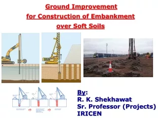
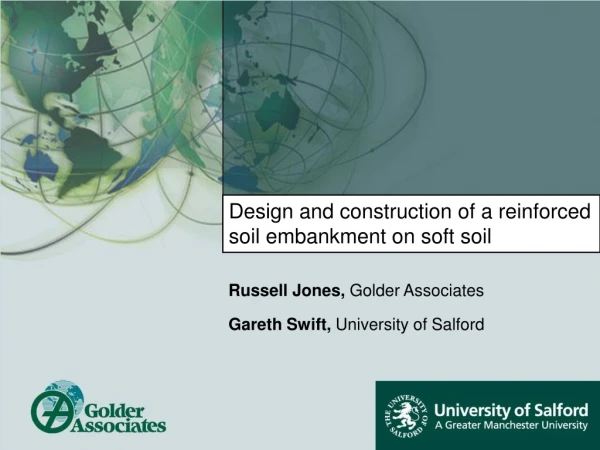
Design and construction of a reinforced soil embankment on soft soil Russell Jones, Golder Associates Gareth Swift, University of Salford
Overview • Background • Site details • Design philosophy • Design issues • Construction issues • Conclusions
Background • Introduction • Site is located south of Basildon in Essex • Bounded by: • Wat Tyler country park on western boundary • Pitsea Marshes (SSSI) along the northern boundary • East Haven Creek along southern boundary (Thames beyond)
Background • Introduction Covers an area of approx. 284ha (>50ha currently operational)
Background • Introduction • Paper and presentation deals with design and construction issues relating to a large leachate lagoon to be constructed on soft, compressible soils • Design carried out in June 2002 • Construction between July 2002 and January 2003 • Lagoon filled to capacity March 2008 • Final Certificate issued by the Panel Engineer July 2008
Background • Client brief: • Minimum leachate capacity of 150,000m3 • Maximum cost of build £1.3 million • Maximum bund height 8mAOD (planning constraint) • ……needs to be buildable!
Background • Additional design constraints: • Ensure stability • Minimise soil imports • Maximise lagoon area (hence, minimise bund height) • Minimise excavation into existing soils
Background • Additionally… • Satisfy requirements of Reservoir Act 1975 • the Act applies to Large Raised Reservoirs,defined as: ‘being designed to hold or capable of holding more than 25,000m3 of water as such above the natural level of any part of the land adjoining the reservoir (including the bed of any stream)’
Overview • Background • Site details • Design philosophy • Design issues • Construction issues • Conclusions
Site Details • Ground conditions • The area is relatively even but groundwater levels close to, or at, the ground surface • Waste dating from the 1950’s underlies the site in a layer between 1m and 7m thick • Waste comprises ash, clinker, glass, cans in hydraulic continuity with the surrounding landfill • This overlies a generally soft stratum of alluvial clays and sands (mv 0.2 – 0.8m2/kN).
Site Details • Ground conditions • A similar, but earlier, lagoon encountered significant difficulties during construction associated with the high groundwater levels and the trafficability of the waste and the soft alluvial material.
Site Details • Ground conditions
Overview • Background • Site details • Design philosophy • Design issues • Construction issues • Conclusions
Design Philosophy • Original design philosophy • Reducing the existing ground level of approximately 3 m AOD to a minimum formation level of 1.0 m AOD • Pumping and dewatering required (estimated quantity 20,000m3 to 75,000m3) • Forming embankment slopes of 1v:4h utilising the excavated waste • Using a single ethylene inter-polymer alloy geomembrane liner on both the base and embankment slopes • Liner manufactured to a specific prefabricated size and shape to suit the design
Design Philosophy • Original design philosophy
Design Philosophy • Original design philosophy
Design Philosophy • Original design philosophy
Design Philosophy • Original design philosophy • Ground conditions are poor at best: • Groundwater/leachate levels at or near to the ground surface; and • Material to be excavated to produce a formation level comprised 1950’s waste of questionable engineering integrity • Dewatering logistically difficult due to up-gradient landfill (with leachate) • Single geomembrane liner not the most effective barrier • Tenderers’ comments
Design Philosophy • Proposed design • No excavation • Reinforced basal platform 20 m wide by 700 mm thick constructed at the existing ground level • Steeper face angles • Reinforced soil perimeter embankment, 5.5 m high • External side slopes 1v:2h • Internal side slopes 1v:1v
Design Philosophy • Original design philosophy
Design Philosophy • Proposed design
Design Philosophy • Proposed design
Design Philosophy • Proposed design • Base area of approximately 32,000 m2 lined with a composite lining system • 2 mm thick Linear Low Density Polyethylene (LLDPE) sheet • Geosynthetic clay liner (GCL) • Underdrainage geocomposite drainage layer to limit hydraulic pressures from the groundwater/leachate and gas • Lining of the perimeter embankment with • 2 mm thick LLDPE geomembrane • Geocomposite drainage layer connected to a piped drainage system
Design Philosophy • Proposed design
Overview • Background • Site details • Design philosophy • Design issues • Construction issues • Conclusions
Design Issues • Proposed design • Since material was limited to on-site sources, the quality would be variable • Side slopes would be steep in order to achieve capacity • Geosynthetic reinforcement, geotextile rather than geogrid to aid dissipation of pore pressures • Primary geotextile reinforcement • Secondary geogrid reinforcement • Granular material used for foundation layer • Cohesive material used for most of embankment but granular material used for upper section
Design Issues • Proposed design
Design Issues • Proposed design
Design Issues • Reinforcement details
Design Issues • Settlement • Final top of embankment = 7.5m AOD • Constructed to = 8m AOD due to anticipated settlement
Design Issues • Material parameters
Design Issues • Value Engineering • Time constraints • Design optimisation during construction • Supported by field trials where possible • ECC form of contract
Design Issues • Value Engineering • NEC/Engineering and Construction Contract • Six Main Options • Option A - Priced with Activity Schedule • Option B - Priced with BQ • Option C - Target with Activity Schedule • Option D - Target with BQ • Option E - Cost Reimbursement • Option F - Management Contract
Design Issues • Contract • NEC/Engineering and Construction Contract • Six Main Options • Option A - Priced with Activity Schedule • Option B - Priced with BQ • Option C - Target with Activity Schedule • Option D - Target with BQ • Option E - Cost Reimbursement • Option F - Management Contract
Design Issues • Stability • A key factor in the design of the perimeter embankments is their stability • Internal – Inside face and outside face • External – Global failure and siding • Major issue is the development of pore water pressure in the sub-grade due to embankment construction • Slope/w and Seep/w used to examine the effects of pore water pressure on stability • Results indicate that the rate of build up and dissipation was critical to stability
Design Issues • Stability • Piezometers used on site to monitor pore water pressures • Construction of toe berms would improve short term stability • Factor of safety >1.3 if ru <0.7 • Toe berms allow increase in ru to 0.8
Design Issues • Stability
Design Issues • Stability • 700mm thick reinforced foundation layer: • 300mm drainage layer • 400mm stability layer
Design Issues • Stability • Typical output:
Design Issues • Groundwater • Geotextile reinforcement allows dissipation of pore pressures in embankment fill • Geocomposite allows dissipation of pore pressures beneath the lagoon • 75mm crushed concrete layer allows dissipation of pore pressures beneath the embankment
Design Issues • Environmental considerations • Leachate containment • 2mm LLDPE geomembrane • GCL • UV protection geotextile • Under drainage • Complete system required to remove gases beneath lining system • 12mm geocomposite
Overview • Background • Site details • Design philosophy • Design issues • Construction issues • Conclusions
Construction Issues • Construction works • Groundwater monitoring • Settlement monitoring
Construction Issues • Construction works Poor ground conditions
Construction Issues • Construction works Generally, a flat lying area in a floodplain
Construction Issues • Construction works
Construction Issues • Construction works • Relatively flat formation level (3.0mAOD) required: • Removal of bushes/trees • Re-profiling of hummocky areas • Elevated ground in NE was excavated • Low area in south backfilled • Existing leachate trench backfilled • Dewatering, where required • Installation of piezometers • Construction of cut-off trench
Construction Issues • Construction works
Construction Issues • Construction works • Basal layer • Separator geotextile on existing ground • 9 mm Drainage geocomposite • 300 mm thick drainage layer • Separator geotextile on drainage layer • 400 mm thick stability layer including two layers of geogrid reinforcement
Construction Issues • Construction works Foundation layer, first layer of geogrid