BASIC DIMENSIONING RULES
BASIC DIMENSIONING RULES. Dimension Terminology. Extension line. Arrowhead. Dimension number. 59. Dimension line. Extension lines. Extension lines should extend 2 mm beyond the dimension line. 40. Extension lines should be offset from the part by 2 mm. Dimension Spacing.

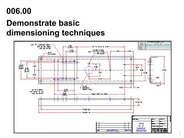
BASIC DIMENSIONING RULES
E N D
Presentation Transcript
Dimension Terminology Extension line Arrowhead Dimension number 59 Dimension line
Extension lines Extension lines should extend 2 mm beyond the dimension line 40 Extension lines should be offset from the part by 2 mm
Dimension Spacing The first row of dimensions will be 12 mm away from the part. 40 20 Any dimension beyond will be 8 mm apart. That is a reference for a 4mm high text. Generally speaking, dimension numbers should be centred between arrowheads.
Arrowheads and numbers Should be 3 times longer than they are wide. Always dimension the actual size of the object, not the scaled size. For metric drawings, omit the use of the millimetre (mm) notation following the number, as millimetres are the default units.
Basic rules • Do not duplicate dimensions and avoid using unnecessary or superfluous dimensions. • Dimensions should be attached to the view that best shows the shape of the feature to be dimensioned. • All horizontal dimensions are read from the bottom edge of the paper and all vertical dimensions are read from the right-hand edge of the paper (aligned system). The number must be placed above the dimension line.
110 40 All horizontal dimensions are read from the bottom edge of the paper and all vertical dimensions are read from the right-hand edge of the paper (aligned system). The number must be placed above the dimension line. 40 50 70 70
Do NOT duplicate dimensions and avoid using unnecessary or superfluous dimensions. The same information should NOT be given in two different ways.The overall dimension should always be given. It should be placed outside of smaller dimensions and be the farthest dimension from the part.
The overall dimension should always be given. It should be placed outside of smaller dimensions and be the farthest dimension from the part. NEVER cross a dimension line and an extension line.
Avoid placing any dimension on the part (inside the view) unless there is no other option. 40 40 BAD PRACTICE GOOD PRACTICE
A dimension should be attached to only one view (i.e., extension lines should not connect two views). 40 40 GOOD PRACTICE BAD PRACTICE
40 Dimensions should be attached to the view that best shows the shape of the feature to be dimensioned. Avoid dimensioning to hidden features. 40 BAD PRACTICE GOOD PRACTICE
Extension lines may cross each other and over other lines on the part, but dimension lines should never be crossed (if possible).
Don’t use a line of the part as a dimension line... ... Never draw a dimension line as a continuation of a line of a view ... Never use a centre line or a line of the view as a dimension line,... … but centre lines can be used as extension lines
Circles and arcs Ø 25 • In general, a circle and an arc greater than 180º is dimensioned by its diametre. An arc less than 180º is dimensioned by its radius. • The dimension lines must be placed at different angles. • No more than two concentric circumferences can be dimensioned in the circular view. The other ones will be dimensioned in the rectangular view. 45 • Dimension cylinders in their rectangular view with a diametre symbol (Ø). • DON’T PLACE THE SYMBOL IN THE CIRCULAR VIEW. 65
When there is lack of space, the dimension number can be placed out of the arrowheads (to the right) If it is not enough room, the arrowheads can be placed out of the extension lines, pointing inwards. When there is no room for the arrowheads, they can be replaced by a point… 45 156 35 50