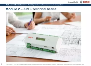
Advanced AMC2 Technical Guide
Learn about the technical data, components overview, memory capabilities, and more of the AMC2 system. Understand the AMC structure, housing, and basic operations with a step-by-step guide included. Explore the AMC memory storage and networking configurations in detail.

Advanced AMC2 Technical Guide
E N D
Presentation Transcript
Content • Technical data • Typical system structure • AMC components overview • PCB’s • Host connection intro • Memory and storage capabilities • Mounting an AMC • Housing • Reset and basic operation with display
AMC Technical overview (I) • Integrated 32Bit, 30MHz Microcontroller • SRAM (256MB), Battery for SRAM and real time clock (RTC) • Serial EEPROM • Real Time Clock • Pluggable Compact Flash card from 64 MB up to 2GB (2GB default delivery) • Host address selectable via DIL sliding switch or software • Host interface, • RS-485 (2- or 4-wire,transfer rate: 38,4 kBit/s, no parity, 8 Bit, 1 Stopbit) • RS-232 • Ethernet • Four Wiegand reader ports (AMC2-4W) or two RS485 reader busses (AMC2-4R4) • Eight relay outputs • Maximum switching power: 60VA • Maximum switching voltage: 30V DC • Maximum switching current: 2A • Eight analog inputs with supervision (2- or 4-state mode) • Tamper contact for enclosures
AMC Technical overview (II) • Power supply AMC: 10V – 30V DC • Display dimensions: 64,8 mm x 13,9 mm 1 line, 16 characters • Power consumption AMC: 5VA • Peripheral devices (using the AMC PBC-60): • Up to 55VA • Constant load 25VA • Connectors: Pluggable screw connectors • Protection Class: IP30 • Environment temperature: 0°C to 45°C • Humidity: Up to 95%, without condensation • Housing material: • Bottom: PPO (UL 94 V-0) • Top: Polycarbonate (UL 94 V-0) • Dimensions (W/H/D): 232mm x 90mm x 63mm (8.9" x 3.5" x 2.4") • Weight: app. 0,53 kg (0.9 pounds)
AMC three tiered structure • AMC works within a three tiered structure: • Data Management Server (DMS) • AMC controller • Card readers (strikes/contacts)
Connecting AMC to Host • Via RS232 directly to AMC controller • With RS232 via MUX RS485 to AMC controller • Via Ethernet (IP) protocol to AMC controller
Opening the AMC controller • Opening the AMC using a screw driver. 1 1 2
AMC PCB overview (upper board) 1. Internal tamper contact 2. DIL switch for RS-485 address selection, protocol and RS-232/RS-485 selection 3. Lithium battery for buffering of static RAM (RTC) 4. Reset push button 5. LCD info display 6. Push button to select the display view 7. Jumper: Potential equalization 8. Jumper: interface selector RS-485 Host connection 9. Configurable RS-485 host interface 10. Docking station for the compact flash 11. Configurable RS-232 host interface 12. 10/100 Mbit/s Ethernet interface
AMC PCB overview (lower board – reverse side) 13. Jumper: Selector for either potential free powered by AMC2 4W internal power supply contacts 14 Jumper: Potential equalization between systems and protective earth (shield)
CF located at AMC board below LCD display AMC memory • AMC controller comes with a 2GB Compact Flash card, which is the maximum size usable. This memory will be used to store: • Door configuration • Cardholders • Events
AMC CF card storage capabilities • The table below shows the number of cardholders and events which an AMC can store on the compact flash card when being offline * The APC-AMC2-xxxCF is equipped with a 2 GB CF card!
For 35mm DIN mounting rail • Bosch rail type nr: • AMC RAIL-250 (250mm) • AMC RAIL-400 (400mm)
Mounting Demounting Mounting the AMC • The AMC can be attached on a standard 35 mm DIN mounting rail via a snap-in mechanism. Attach the AMC into the upper edge of the mounting rail, then push down the AMC and snap it onto the rail by pushing it towards the back.
LCD info display • By pushing the info button on the AMC the following data will be rotate on the LCD info display:
Resetting an AMC • It’s rarely possible that an AMC is in an undefined state and doesn’t react properly, e.g. a download fails or was interrupted unexpected. In those cases it might be necessary to reset it. To do so follow this procedure • Insert the provided screwdriver into the hole on the left hand side of the display, as shown in the figure below • Push the reset button for at least three seconds • The AMC will reset and reboots • Now it is possible to reconfigure the AMC2 from the beginning • When online and connected to a host application the download of firmware and configuration data will start automatically after a while With the help of the info LCD display you could check the software version afterwards.
Resetting the network configuration • To Reset the network configurations: • Reset the AMC as described before • Open the upper case of the AMC2 as described before • Set all six DIL switches of the RS-485 selector to ON • Press the tamper switch on the upper left side of the board • The AMC2 will now have the following network configuration: • DHCP = 0 • IP = 127.0.0.1
Self-check • Answer the questionaire „AMC-Q02“ (under construction)