Download
1 / 47
580 likes | 989 Vues
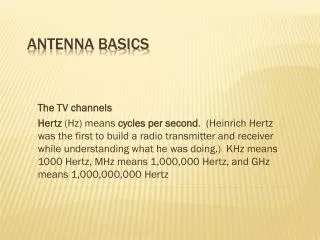
Antenna Basics Module 3A. Jerry Bernardini Community College of Rhode Island. Presentation Reference Material. The California Regional Consortium for Engineering Advances in Technological Education (CREATE) project CWNA Certified Wireless Network Administration Official Study Guide

E N D
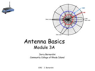
Antenna BasicsModule 3A Jerry Bernardini Community College of Rhode Island CCRI J. Bernardini
Presentation Reference Material • The California Regional Consortium for Engineering Advances in Technological Education (CREATE) project • CWNA Certified Wireless Network Administration Official Study Guide (PWO-104), David Coleman, David Westcott, 2009, Chapter-1 • Cisco Wireless technology • http://martybugs.net/ Wireless Networking J. Bernardini
Antenna Principles • A theoretical isotropic antenna has a perfect 360º vertical and horizontal beamwidth • The Isotropic antenna the a reference for all antennas (dBi) • Antennas are symmetrical: A receiving antenna has the same characteristics as a transmitter • Antennas have gain in particular directions • Direction other than the main intended radiation pattern, are typically related to the main lobe gain CCRI J. Bernardini
Different Antennas CCRI J. Bernardini
Key Antenna Terms • Plane H (H-Horizontal) • Plane E(E-Elevation) • Lobes • Directional • Omnidirectional • Beamwidth • Bandwidth • Polarization • Vertical (Elevation) • Horizontal (Azimuth) • Diversity • VSWR • Antenna Accessories CCRI J. Bernardini
Antenna Gains CCRI J. Bernardini
Antenna Characteristics • Main beam is the region around the direction of maximum radiation The main beam is centered at 90 degrees • Sidelobes are smaller beams that are away from the main beam. Radiate in directions other than the main beam and can never be completely eliminated. • Half Power Beamwidth (HPBW) is the angular separation in which the magnitude of the radiation pattern decrease by 50% (or -3 dB) from the peak of the main beam. • Null to Null Beamwidth. the angular separation from which the magnitude of the radiation pattern decreases to zero (negative infinity dB) away from the main beam. CCRI J. Bernardini
H-Plane-Azimuth 0o Beamwidth -3dB 270o 90o 180o CCRI J. Bernardini
Beamwidths 0 dB -3dB CCRI J. Bernardini
Polar Pattern Analysis 50o Beam CCRI J. Bernardini
Dipole H and E Planes CCRI J. Bernardini
5.8 dBi Omnidirectional Antenna, CCRI J. Bernardini
Side View (Vertical Pattern) Vertical Beamwidth New Pattern (with Gain) Top View (Horizontal Pattern) Typical Dipole Antenna Beam Pattern • Starting from an Isotropic antenna energy lobes are ‘pushed in’ from the top and bottom • Higher gain • Smaller vertical beamwidth • Larger horizontal lobe • Typical dipole pattern CCRI J. Bernardini
2.4 GHz Omni-Directional Antennas • 2 dBi Dipole "Standard Rubber Duck" CCRI J. Bernardini
Rubber Ducky Antenna Construction Each half of the dipole is a 1/4 wavelength, with the length corrected based on the velocity of the coax being used. Assuming a centre frequency for 802.11b of 2.441GHz, a 1/4 wavelength in free space is 30.7mm. Length of the metal casing is approx 24mm, with a total length of 50mm. Thin wire whip protruding from the top of the metal casing is approx 26mm Metal casing is a "decoupler", and is typically used to tune the antenna, by moving the decoupler up and down to vary the VSWR . CCRI J. Bernardini
High Gain Omni-Directionals • More coverage area in a circular pattern • Energy level directly above or below the antenna will become lower CCRI J. Bernardini
2.4 GHz Omni-Directional Antennas • 5.2 dBi Mast Mount Vertical CCRI J. Bernardini
2.4 GHz Omni-Directional Antennas • 5.2 dBi Pillar Mount Diversity CCRI J. Bernardini
2.4 GHz Diversity Omni-Directional Antennas • 2 dBi Diversity Omni-Directional Ceiling Mount CCRI J. Bernardini
2.4 GHz Omni-Directional Antennas • 12 dBi Omni-Directional (Outdoor only) CCRI J. Bernardini
2.4 GHz Diversity Antennas • 6.5 dBi Diversity Patch Wall Mount – 55 degree CCRI J. Bernardini
2.4 GHz Directional Antennas (cont.) • 6 dBi Patch Antenna – 65 degree CCRI J. Bernardini
2.4 GHz Directional Antennas (cont.) • 8.5 dBi Patch Antenna – 60 degree CCRI J. Bernardini
2.4 GHz 13.5 dBi Yagi Antenna • – 25 degree Beamwidth CCRI J. Bernardini
2.4 GHz Directional Antennas (cont.) • 21 dBi Parabolic Dish Antenna – 12 degree CCRI J. Bernardini
Antenna Polarization E-Plane is parallel to the antenna H-Plane is perpendicular to the antenna Horizontal Polarization – the Electric field is parallel to the ground Vertical Polarization – the Electric field is perpendicular to the ground CCRI J. Bernardini
FCC Rules 2.4 GHz EIRP • Point-to-Multipoint • FCC allows increasing the gain of an antenna/cable system if the transmitter power is reduced below 30 dBm in a 1:1 ratio • Reduce Transmit Power below maximum of 30 dBm by 1 dBm and increase antenna/cable system gain by 1dBi • Point-to-Point • Maximum of 36 dBm EIRP • Installations – 30 dBm maximum transmitter power with 6 dBi in gain attributed to antenna and cable combination • FCC allows exceeding the 36 dBm EIRP in Point-to-Point installations using the 3:1 rule • Reduce Transmit Power below maximum of 30 dBm by 1 dBm and increase antenna/cable system gain by 3 dBi CCRI J. Bernardini
Voltage Standing Wave Ratio (VSWR) • A measure of the change in impedance to an AC signal. • Ratio of the Maximum Voltage to Minimum Voltage in an RF system. • Typical Values: 1.1 : 1 to 1.5 :1 (1:1 Ideal system; impossible to obtain) • Measure of the amount of energy sent to the antenna that reflects back to the transmitter. • Too large a VSWR will reflect too much energy back to the transmitter and damage the transmitter • Output of Transmitter must match Cable , which matches Antenna impedance • Return Loss – Ratio of Reflected voltage to Transmitter voltage in dB. Ideally this should be small CCRI J. Bernardini
VSWR Table CCRI J. Bernardini
Impedance Matching Effects • When the impedances are matched –Half of the source power is delivered to the load and half is dissipated within the (equivalent) generator as heat • For receiving antenna, half the power captured is lost as heat in the antenna elements, the other part being reradiated (scattered) back into space • When the antenna impedance is not matched to the transmitter output impedance (or to the receiver input impedance) or to the transmission line between them, impedance-matching devices must be used for maximum power transfer. • -impedance-matching devices are used They are usually narrow-band • Transmission lines often have significant losses CCRI J. Bernardini
Antenna Diversity • Receiver selects the stronger antenna signal compensating for multipath • Frame by frame antenna sampling to determine strongest signal • Transmitting occurs on the previous strong-signal antenna =Transmit Diversity • Not all access points have Trasmitter Diversity CCRI J. Bernardini
Multiple-Input Multiple-Output (MIMO) • A sophisticated form of antenna diversity • Multipath signals are Space Time Coding (STC) processed to improve receiver performance • IEEE 802.11n employs MIMO • Not specified with 802.11a, b,g CCRI J. Bernardini
Antenna Path Considerations • Radio line of sight • Height of Earth bulge • Fresnel Zone Radius • Height of Obstacles CCRI J. Bernardini
Line of sight! Line of Sight • The following obstructions might obscure a visual link: • Topographic features, such as mountains • Curvature of the Earth • Buildings and other man-made objects • Trees CCRI J. Bernardini
Longer Distances • Line of Sight disappears at 6 miles (9.7 Km) due to the earth curve CCRI J. Bernardini
Fresnel Zone Fresnel Zone CCRI J. Bernardini
Improving Fresnel Effect Raise the antenna New structure Existing structure Different mounting point Remove trees CCRI J. Bernardini
Site to Site Fresnel Zone • Antenna Height • Fresnel zone consideration • Line-of-Sight over 25 miles (40 Km) hard to implement Antenna Height (Value “H”) Total Distance Fresnel @ 60% (Value “F”) Earth Curvature (Value “C”) CCRI J. Bernardini
Antenna Alignment Line of Sight CCRI J. Bernardini
Antenna Installation Towers and antennas may require permits and must meet local regulations CCRI J. Bernardini
Grounding • Antenna towers must be ground to protect from lightning Grounding Rods (6 ft r Antenna CCRI J. Bernardini
5 GHz Integrated Antenna • Innovative 5 GHz Combo Antenna: • Wall Mount: Fold antenna flat against access point housing for 6 dBi gain patch antenna • Ceiling Mount: Fold antenna out at a 90° angle for 5 dBi gain omni antenna In 6 dBi patch position In 5 dBi omni position CCRI J. Bernardini
2.4 GHz Accessories CCRI J. Bernardini
RP-TNC Connectors CCRI J. Bernardini
Lightning Arrestor CCRI J. Bernardini
Lightning Arrestor • Designed to protect LAN devices from static electricity and lightning surges that travel on coax transmission lines • RP-TNC connectors used on all Cisco Antennas To Antenna Lug Lockwasher Nut Ground Wire From RF Device CCRI J. Bernardini