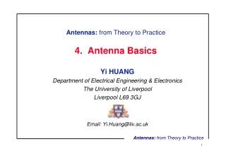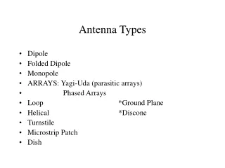
Antenna Basics
The TV channels Hertz (Hz) means cycles per second . (Heinrich Hertz was the first to build a radio transmitter and receiver while understanding what he was doing.) KHz means 1000 Hertz, MHz means 1,000,000 Hertz, and GHz means 1,000,000,000 Hertz. Antenna Basics.

Antenna Basics
E N D
Presentation Transcript
The TV channels Hertz (Hz) means cycles per second. (Heinrich Hertz was the first to build a radio transmitter and receiver while understanding what he was doing.) KHz means 1000 Hertz, MHz means 1,000,000 Hertz, and GHz means 1,000,000,000 Hertz Antenna Basics
Frequency: Wavelength (meters): VLF very low frequency 3 KHz – 30 KHz 100 Km – 10 Km LF low frequency 30 KHz – 300 KHz 10 Km – 1 Km AM Radio MF medium frequency 300 KHz – 3 MHz 1 Km – 100 m Short wave HF high frequency 3 MHz – 30 MHz 100 m – 10 m TV and FM VHF very high frequency 30 MHz – 300 MHz 10 m – 1 m UHF ultra high frequency 300 MHz – 3 GHz 1 m – 100 mm Satellite SHF super high frequency 3 GHz – 30 GHz 100 mm – 10mm EHF extremely high freq. 30 GHz – 300 GHz 10 mm – 1 mm The radio frequency spectrum is divided into major bands:
VHF Low Band: | VHF High Band: Channel Freq. (mhz) | (mhz) 2 54-60 | 7 174-180 3 60-66 | 8 180-186 4 66-72 | 9 186-192 | 10 192-198 5 76-82 | 11 198-204 6 82-88 | 12 204-210 | 13 210-216 Frequency allocations for TV channels in the U.S.
UHF Band: Chan Freq (MHz) | Chan Freq (MHz) | Chan Freq (MHz) | Chan Freq (MHz) 14 470-476 | 32 578-584 | 50 686-692 | 68 794-800 15 476-482 | 33 584-590 | 51 692-698 | 69 800-806 16 482-488 | 34 590-596 | 52 698-704 | 70 806-812 17 488-494 | 35 596-602 | 53 704-710 | 71 812-818 18 494-500 | 36 602-608 | 54 710-716 | 72 818-824 19 500-506 | 37 608-614 | 55 716-722 | 73 824-830 20 506-512 | 38 614-620 | 56 722-728 | 74 830-836 21 512-518 | 39 620-626 | 57 728-734 | 75 836-842 22 518-524 | 40 626-632 | 58 734-740 | 76 842-848 23 524-530 | 41 632-638 | 59 740-746 | 77 848-854 24 530-536 | 42 638-644 | 60 746-752 | 78 854-860 25 536-542 | 43 644-650 | 61 752-758 | 79 860-866 26 542-548 | 44 650-656 | 62 758-764 | 80 866-872 27 548-554 | 45 656-662 | 63 764-770 | 81 872-878 28 554-560 | 46 662-668 | 64 770-776 | 82 878-884 29 560-566 | 47 668-674 | 65 776-782 | 83 884-890 30 566-572 | 48 674-680 | 66 782-788 | 31 572-578 | 49 680-686 | 67 788-794 | Frequency allocations for UHF
Channels 70-83 were de-allocated in 1982. They are now cell phone frequencies. Channels 52-69 have been de-allocated on February 17, 2009. Channel 37 is allocated to radio astronomy . NOte -2 below is part of the switch to Dtv
Any of these channels could contain either an analog channel or a digital channel. Note that “channel 25-1” is a virtual channel name and does not indicate what channel the station physically occupies. Channels 2-13 are the VHF channels. They are split into two groups so that antennas will work better: In general, an antenna designed for frequency N will also work well at 3N, but very poorly at 2N. Basics
The wavelength of a radio wave is: λ = 300/F where F is the frequency in mega-Hertz and λ is the wavelength in meters. Antenna elements are typically about a half-wavelength long. λ = 186000 miles /F where F is the frequency in Hertz and λ is the wavelength in mile (you would need to convert to feet). wavelength
Decibels (dB) are commonly used to describe gain or loss in circuits. The number of decibels is found from: Gain in dB = 10log(gain factor) or: Decibels
In some situations this is more complicated than using gain or loss factors. But in many situations, decibels are simpler. For example, suppose 10 feet of cable loses 1 dB of signal. To figure the loss in a longer cable, just add 1 dB for every 10 feet. In general, decibels let you add or subtract instead of multiply or divide. Decibels
20 dB = gain factor of 100 10 dB = gain factor of 10 3 dB = gain factor of 2 (actually 1.995) 0 dB = no gain or loss -1 dB = a 20% loss of signal -3 dB = a 50% loss of signal -10 dB = a 90% loss of signal There are some special numbers you might want to memorize:
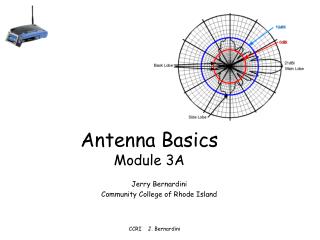
Whether a signal is receivable is determined by the signal to noise ratio (S/N). • For TVs there are two main sources (classes) of noise: • Atmosphere noise. There are many types of sources for this noise. A light switch creates a radio wave every time it opens or closes. Motors in some appliances produce nasty RF (radio frequency) noise. • Receiver noise. Most of this noise comes from the first transistor the antenna is attached to. Some receivers are quieter than others. • Receiver noise dominates on the VHF and UHF bands, and atmospheric noise is usually insignificant. On an analog channel, noise looks like snow. If there were only a barely perceptible amount of snow, this would correspond to how noise-free a DTV signal must be for a DTV receiver to lock-on to it. Noise
Many people think that connecting an external amplifier to the antenna will improve the performance of the antenna. This is usually wrong. Receivers always enough gain built in to work with an appropriate signal. The problem is that you need a strong enough signal from the antenna to begin with. Then if you have a long run or multiple taps you can add an amplifier to boost the signal. The receiver has an Automatic Gain Control circuit, AGC, which will reduce strong signals. The AGC makes all stations the same strength at the demodulator. When you add a preamplifier, the TV receiver lowers its own gain, usually by an equivalent amount. So when do you use an amplifier? Signal Amplifiers, Preamplifiers
Normally the signal to noise ratio will be set by the receiver’s first transistor. But if an external amplifier is added, the first transistor in that amplifier determines the S/N ratio. (Since the external amp will greatly magnify its own noise as well as the signal, the receiver’s noise becomes insignificant.) Since there is no reason to think the external amp’s first transistor is quieter than the receiver’s first transistor, there is generally no benefit to the S/N ratio from an external amplifier. Signal to noise - S/N ratio
an external amplifier will compensate for signal loss in the cable if the amplifier is mounted at the antenna. Without this amplifier, a weak signal, just above the noise level at the antenna, could sink below the noise level due to loss in the cable, and be useless at the receiver. external amplifier
RG-6 will lose 1 dB of the signal every 18 feet at channel 52. For a DTV channel, 1 dB can be the difference between dropouts every 15 minutes (probably acceptable) and every 30 seconds (unwatchable). Recommendation- use a mast-mounted amplifier whenever the cable length exceeds 20 feet. If you are in a good-signal area or you have no high-numbered UHF channels, you may be able to get by without one. mast-mounted amplifier
The Mast mounted amplifier should have a gain equal to the loss in the cable (for your highest channel) plus another 10 dB (to keep the receiver’s first transistor out of the picture The amplifier can usually exceed this target by another 10 dB without causing trouble. If you follow the above rule, the cable length becomes irrelevant, and reducing the cable length yields no benefit under normal home construction sites (antenna cables limited to ~ 100’ or less). rule for amplifier power
When figuring the cable loss, be sure to include the loss in any splitters and baluns. If a 2-to-1 splitter were 100% efficient then you would figure a 3 dB loss since each TV gets half of the power. But splitters are usually 80% to 90% efficient. 2-to-1 splitter 3.5-4 dB 3-to-1 splitter 5-6 dB 4-to-1 splitter 7-8 dB 75-to-300balun 0.2-2 dB (a balun is an adapter)
You might not need an amplifier if the antenna is too big. But an amplifier can never make up for an antenna sinal that is too small.
Actually there is a reason to think the external amplifier is quieter than the receiver. Long ago designers made an effort to make the TV’s first amplifier stage very quiet. But now 90% of homes use cable or satellite boxes (strong sources) and most of the rest are rural homes using antennas that have mast-mounted amplifiers. So the TV’s noise is rarely a factor. Some TV makers no longer put any effort into making their sets quiet. Receiver noise
Suppose you live in an apartment 15 miles from the transmitter. Your indoor antenna mostly works, but you are troubled by dropouts and some snow appears on analog channels. Will adding an amplifier right at the TV improve things? Yes, if it is quieter than the TV. Unfortunately TV makers see no reason to publish the noise figures for their receivers. So buying an amplifier for an indoor antenna is a total crapshoot. recommended to try an amplifier, but make sure you can return it if it is no help.
Twinlead (ribbon cable) used to be common for TV antennas. It has its advantages. But due to its unpredictability when positioned near metal or dielectric objects, it has fallen out of favor. Such objects, even if not touching the cable, cause a portion of the signal to bounce, return to the antenna, and get retransmitted. Transmission cable
Coaxial cable is recommended. It is fully shielded and not affected by nearby objects. Transmission cable has a feature called its characteristic impedance, which for TV coax should always be 75 ohms. (50-ohm coaxial cable is also common. Avoid that cable.) Although rated in ohms, this has nothing to do with resistance. A resistor converts electric energy into heat. The “75 ohms” of a coaxial cable does not cause heat. Coaxial cable
But coax also has ordinary resistance (mostly in the center conductor) and thus loses some of the signal, converting it into heat. The amount of this dissipation (loss) depends on the frequency as well as the cable length. Type: Center conductor: Cable diameter: RG-59 20-23 gauge 0.242 inches RG-6 18 gauge 0.265 inches RG-11 14 gauge 0.405 inches resistance
If the mast-mounted amplifier gain exceeds the cable loss then it shouldn’t matter what cable you use. But there are two problems with this: • 1. Some cable has incomplete shielding. This is most common for RG-59, another reason to avoid it. • 2. When the cable run is longer than 200 feet, the low-numbered channels can become too strong relative to the high-numbered channels. In this case, RG-11 or an ultra-low-loss RG-6 is recommended. (These alternatives are expensive.) Alternatively, frequency compensated amplifiers will work. mast-mounted amplifier gains
Recommendation - use RG-6 for all TV antennas. It can be stapled in place using a staple gun with common 9/16” T25 staples. How long the cable lasts depends solely on how long you can keep water out of it. 3M Vinyl Electrical Tape is a good water proofer. Even better is an asphalt putty called “Coax Seal”, but it is so tenacious it should not be used for temporary connections. Cover the connectors completely. Sealing connections
A balun is an adapter that adapts a balanced line to unbalanced line. If a balanced transmission line (such as twinlead) is connected directly to an unbalanced line (such as coaxial cable) the two lines become a long-wire antenna, which is undesirable for VHF and UHF. All baluns are passive bi-directional devices. They are usually above 90% efficient. Baluns
4-to-1 balun - This will connect 300-ohm twinlead to 75-ohm coaxial cable. This balun is usually a ferrite transformer. This is the type you find mounted at the antenna 1-to-1 balun - This will connect a 75-ohm balanced load to 75-ohm coaxial cable. This balun is often just some ferrite beads slipped over the coax. Baluns continued
Comparing some common 4-to-1 baluns The 15-1253 is not suitable for outdoor use.