Antenna Fundamentals
450 likes | 1.03k Vues
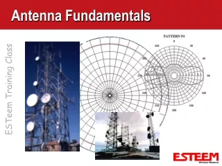
Antenna Fundamentals. Decibels (dB). Used for all mathematical calculations in the radio world. dB is a logarithmic number dB =10 log (linear number) A gain of 2 = 10 log (2) = 3 dB A gain of 4 = 10 log (4) = 6 dB When a number doubles it goes up 3 dB

Antenna Fundamentals
E N D
Presentation Transcript
Decibels (dB) • Used for all mathematical calculations in the radio world. • dB is a logarithmic number • dB =10 log (linear number) • A gain of 2 = 10 log (2) = 3 dB • A gain of 4 = 10 log (4) = 6 dB • When a number doubles it goes up 3 dB • When a number reduces by 1/2, it goes down -3 dB • To multiply linear numbers you add logarithms • To divide linear numbers you subtract logarithms
Antenna Gain • Antenna Gain measure in decibels (dB) • Double every 3 dB • Effective Radiated Power (ERP) = Tx Power + Antenna Gain - Feedline Losses • Received Signal = Rx Power + Antenna Gain - Feedline losses • As Antenna Gain increases Antenna Pattern becomes more directional
Radiation Patterns RF Energy • Omni-Directional • Radiates RF energy in all directions from antenna Antenna Top View
RF Basics - Omni-Directional Antennas • Omni-Directional Antenna • Radiates RF energy in all directions from antenna • Usually used at the Master and Repeater Nodes Omni-directional Antenna Vertical Polarized 360 degrees Side View Radiation Pattern Vertical Polarization Top View Radiation Pattern Vertical Polarization
RF Basics - Antenna Gain • As Antenna Gain increases the Antenna Pattern becomes more directional Omni- Directional Antenna Shown Below 3 dB Points 360 degrees Remains Unchanged Vertical Beam Width (degrees) Top View Radiation Pattern Vertical Polarization Side View Radiation Pattern Vertical Polarization
Radiation Patterns RF Energy • Directional • Compresses RF Energy in one direction Antenna Top View
RF Basics - Directional Antennas 3 dB Points 3 dB Points Vertical Beam Width (degrees) Horizontal Beam Width (degrees) Back Lobe Back Lobe Top View Radiation Pattern Vertically Polarized Side View Radiation Pattern Vertically Polarized • Directional • Radiates RF energy in one direction • Usually used at Remote Nodes in a Point to Multi-point system or Point to Point Site
RF Basics - Antenna Gain • As Antenna Gain increases the Antenna Pattern becomes more directional Directional Antenna Shown Below 3 dB Points 3 dB Points Horizontal Beam Width (degrees) Vertical Beam Width (degrees) Back Lobe Back Lobe Top View Radiation Pattern Vertically Polarized Side View Radiation Pattern Vertically Polarized
Antenna Polarization Directional Antenna Vertical Polarized • Vertical Or Horizontal Polarization • Polarization is the radiating element referenced to earth • All nodes must be the same polarization • Cancellation of signal if mismatched • Vertical Polarization for Most Radio Applications • Mixture of Omni and Directional Antennas • No Horizontal Polarization of Omni-Directional Omni-directional Antenna Vertical Polarized
Antenna Types • 1/2 Wave Antenna • Close to Isotropic Radiation • Approximately 3 dB gain • No ground planes needed
Antenna Types • 1/4 Wave Antenna • Unity Gain • Requires Ground Planes • “Cone of Silence” above and below antenna Cone of Silence Cone of Silence
Antenna Types • Yagi • High gain • Directional • Horizontal Beamwidth • Vertical Beamwidth
Antenna Impedance • 50 Ohm Load Is the Industry Standard • Based on 1/4 Wave Antenna • Antenna Impedance Must Match Feedline Impedance and Transmitter Output Impedance • A Mismatch Will Induce Standing Waves Which Will Reduce Radiated Power
RF Basics - Feedlines • Feedline • Pipeline for RF Energy From Radio to/from Antenna • Different Cable Types Have Different Losses • The lower the loss the more expensive the cable • Losses Based Upon Length & Frequency • Expressed in dB/100 ft. by the manufacturer • The higher the frequency, the more attenuation in cables, connectors, etc. • All feedlines and connectors induce losses to RF energy
RF Basics - Feedline Attenuation Table Feedline Attenuation (- dB/100 ft.)
Types of Feedlines • RG-58 Cable • Only use on very short runs (< 10 feet) • Good on licensed (<1 GHz) only • Very flexible • 72-79 MHz = 3.8 dB per 100 feet • 150-174 MHz = 5.2 dB per 100 feet • 400-500 MHz = 11 dB per 100 feet
Types of Feedlines • LMR-195 Cable • Only use on very short runs (2.5 foot standard length) • Very flexible • Good up to 2.4 GHz • 72-79 MHz = 3.0 dB per 100 feet • 150-174 MHz = 4.4 dB per 100 feet • 400-500 MHz = 7.8 dB per 100 feet • 2.4 GHz = 19 dB per 100 feet
Types of Feedlines • RG-8 Cable • Good for feedline runs up to 50 feet (Licensed Radios) • Workable losses up to UHF frequencies • 72-79 MHz = 1.5 dB per 100 feet • 150-174 MHz = 2.3 dB per 100 feet • 400-500 MHz = 4.4 dB per 100 feet • 2.4 GHz = 10 dB per 100 feet • Both rigid and flexible cable available
Types of Coax • 1/2 Inch Heliax • Recommend for feedline runs over 50 feet • Very low loss • 72-79 MHz = .6 dB loss per 100 feet • 150-174 MHz = .8 dB per 100 feet • 400-500 MHz = 1.5 dB loss per 100 feet • 2.4 GHz = 3.74 dB loss per 100 feet • Very rigid • Higher cost per foot than RG-8
Connector Types • TNC • Input connectors on most ESTeems • UHF • Input to most antennas • N-Type • Input to lightning arrestor and some antennas • Reverse Polarity • All unlicensed radio systems require “unique” connectors
Standing Wave Ratio (SWR) • Ratio of Maximum to Minimum Values in Standing Wave Pattern • Voltage (VSWR) or Current • Mismatch in Impedance (Antenna or Cable) Will Induce Standing Waves • Measurement of Forward and Reflected Power Most Field Expedient • Wattmeter
SWR Measurement • Maximum = 10% Reflected Power • ESTeem commands • Radio ON command for serial • Advanced Menu 195E To Antenna Transceiver Directional Watt Meter
Typical Outdoor Antenna Block Diagram Antenna Interface Cable Feedline User’s Device Lightning Arrestor 12 VDC Power Supply
Typical Indoor/Mobile Antenna Diagram Antenna Interface Cable Feedline User’s Device 12 VDC Power Supply
Typical Model 195E Mounting Directional Antennas Unit Shown With Rubber Duct Antennas Model 195E Outdoor Fixed Base Hardware Diagram Omni-Directional Antenna External Antennas Antenna Feedline Weather Proof Boot Weather Proof Boot Direct Pole Mount Pole Mounting Kit EST P/N AA195PM Model 195ESeries Weather Proof Front Cover Weather Proof Boot Direct Mount Antennas Power Over Ethernet Cable Ethernet Surge Protection EST P/N AA166 PoE Power Supply EST P/N AA175 Ethernet CAT-5e Cable 300 ft. maximum Ethernet CAT 5e Cable EST P/N: AA09.2 To LAN Interface
RF Filters (Licensed Frequencies) • Bandpass Filter • Filters out all radio frequencies except the operating frequency • Notch Filter • Filters out a specific frequency in the frequency band • Combiner/Duplexer • Allows two transceivers to share a common antenna and coax • Minimum frequency separation
Mobile Installation • Antenna Uses Vehicle as Ground Plane • No Lightning Arrestor Needed • Antenna Pattern Dependent On Vehicle Mounting Location
Lightning Protection • Ground Antenna and Lightning Arrestor to Same Ground Potential • Protect Power Supply • Protect Data Cable DC Grounded Antenna Multi-Strike Lightning Arrestor Earth Ground
Weather Proofing • Silicone On Connector Threads • Do not get sealant on center conductor • Wrap RF Connector With Electrical Tape • Wrap beyond the connector of easy removal • Form Vinyl Mastic Pad Over Connection • Coat Entire Connector With Skotchkote Electrical Coating