Antenna Fundamentals
1.97k likes | 6.15k Vues
Antenna Fundamentals. Introduction. The antenna is the interface between the transmission line and space Antennas are passive devices ; the power radiated cannot be greater than the power entering from the transmitter

Antenna Fundamentals
E N D
Presentation Transcript
Introduction • The antenna is the interface between the transmission line and space • Antennas are passive devices; the power radiated cannot be greater than the power entering from the transmitter • When speaking of gain in an antenna, gain refers to the idea that certain directions are radiated better than others • Antennas are reciprocal - the same design works for receiving systems as for transmitting systems
Decibels (dB) • Used for all mathematical calculations in the radio world. • dB is a logarithmic number • dB =10 log (linear number) • A gain of 2 = 10 log (2) = 3 dB • A gain of 4 = 10 log (4) = 6 dB • When a number doubles it goes up 3 dB • When a number reduces by 1/2, it goes down -3 dB • To multiply linear numbers you add logarithms • To divide linear numbers you subtract logarithms
Antenna Gain • Antenna Gain measure in decibels (dB) • Double every 3 dB • Effective Radiated Power (ERP) = Tx Power + Antenna Gain - Feedline Losses • Received Signal = Rx Power + Antenna Gain - Feedline losses • As Antenna Gain increases Antenna Pattern becomes more directional
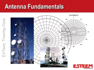
Radiation Patterns RF Energy • Omni-Directional / Isotropic • Radiates RF energy in all directions from antenna Antenna Top View
RF Basics - Omni-Directional Antennas • Omni-Directional / Isotropic Antenna • Radiates RF energy in all directions from antenna • Usually used at the Master and Repeater Nodes Omni-directional Antenna Vertical Polarized 360 degrees Side View Radiation Pattern Vertical Polarization Top View Radiation Pattern Vertical Polarization
RF Basics - Antenna Gain • As Antenna Gain increases the Antenna Pattern becomes more directional Omni- Directional Antenna Shown Below 3 dB Points 360 degrees Remains Unchanged Vertical Beam Width (degrees) Top View Radiation Pattern Vertical Polarization Side View Radiation Pattern Vertical Polarization
Radiation Patterns RF Energy • Directional • Compresses RF Energy in one direction Antenna Top View
RF Basics - Directional Antennas 3 dB Points 3 dB Points Vertical Beam Width (degrees) Horizontal Beam Width (degrees) Back Lobe Back Lobe Top View Radiation Pattern Vertically Polarized Side View Radiation Pattern Vertically Polarized • Directional • Radiates RF energy in one direction • Usually used at Remote Nodes in a Point to Multi-point system or Point to Point Site
RF Basics - Antenna Gain • As Antenna Gain increases the Antenna Pattern becomes more directional Directional Antenna Shown Below 3 dB Points 3 dB Points Horizontal Beam Width (degrees) Vertical Beam Width (degrees) Back Lobe Back Lobe Top View Radiation Pattern Vertically Polarized Side View Radiation Pattern Vertically Polarized
Antenna Polarization Directional Antenna Horizontal Polarized Directional Antenna Vertical Polarized • Vertical Or Horizontal Polarization • Polarization is the radiating element referenced to earth • All nodes must be the same polarization • Cancellation of signal if mismatched • Vertical Polarization for Most Radio Applications • Mixture of Omni and Directional Antennas • No Horizontal Polarization of Omni-Directional Omni-directional Antenna Vertical Polarized
Antenna Types • 1/2 Wave Antenna • Close to Isotropic Radiation • Approximately 3 dB gain • No ground planes needed
Antenna Gain Specifications • dBi means decibels with respect to an isotropic radiator • dBd means decibels with respect to an ideal half-wave dipole in its direction of maximum radiation • The gain of a dipole is 2.14 dBi
Beamwidth The width of this bean is defined as the angle between its half-power points. A half-wave dipole has a beamwidth of about 79º in one plane and 360º in the other
Antenna Theory • An antenna is a transducer designed to transmit or receive electromagnetic waves. • The official IEEE definition of an antenna is “That part of a transmitting or receiving system that is designed to radiate or receive electromagnetic waves”. Radiation from an Antenna • Radiation of antenna can be explained by using capacitor concept. • During positive half cycle of current capacitor charges with upper plate positive and lower plate negative chargers . This creates electric line of forces and there direction is from top to bottom. • In anticlockwise direction of current, polarity reverses and electric lines of forces become bottom to top.
Radiation From an Antenna • When current flowing in one direction and is required to reverse their direction rapidly, those lines of forces at the extreme edge are unable to make this change with sufficient rapidly and are forced to out of the system. • In this way a certain amount of energy, stored in capacitor is radiated during each cycle. This affect increases with frequency, so that at radio frequencies, efficient radiations obtained from the conductor i.e. antenna.
Field Regions of Antenna • The fields surrounding an antenna are divided into 3 principle regions: • Reactive Near Field • Radiating Near Field or Fresnel Region • Far Field or Fraunhofer Region
Field Regions of Antenna Reactive Near Field Region • In the immediate vicinity of the antenna, we have the reactive near field. • In this region, the fields are predominately reactive fields, which mean the E- and H- fields are out of phase by 90 degrees to each other. • In this region, energy is only stored and no energy is dissipated. The boundary of this region is commonly given as: Where R is the distance from the antenna surface, D is the largest dimension of the antenna and λ is the wavelength
Field Regions of Antenna Radiating Near Field (Fresnel) Region • The radiating near field or Fresnel region is the region between the near and far fields. • Reactive fields are smaller in this field as compared to the reactive near-field region and the radiation fields dominate. The outermost boundary for this region is given by: Where R is the distance from the antenna surface, D is the largest dimension of the antenna and λ is the wavelength
Field Regions of Antenna Far-field region (Fraunhofer region) • The region beyond is the far field region. • In this region, the reactive fields are absent and only the radiation fields exist; with the E- and H-fields orthogonal to each other and the direction of propagation as with plane waves. • The far field region is the most important, as this determines the antenna's radiation pattern. • Also, antennas are used to communicate wirelessly from long distances, so this is the region of operation for most antennas.
Antenna Performance Parameters Radiation Pattern An antenna radiation pattern or antenna patternis defined as “a mathematical function or a graphical representation of the radiation properties of the antenna as a function of space coordinates”. In most cases, the radiation pattern is determined in the far field region and is represented as a function of the directional coordinates. Directivity Directivity of an antenna defined as “the ratio of the radiation intensity in a given direction from the antenna to the radiation intensity averaged over all directions”. It may be regarded as the ability of the antenna to direct radiated power in a given direction.
Antenna Performance Parameters Antenna Efficiency The efficiency of an antenna relates the power delivered to the antenna and the power radiated or dissipated within the antenna. The antenna efficiency (or radiation efficiency) can be written as the ratio of the radiated power to the input power of the antenna: Antenna Gain The term Antenna Gain describes how much power is transmitted in the direction of peak radiation to that of an isotropic source. Antenna Gain (G) can be related to directivity (D) by: Thus, Antenna gain is defined as antenna directivity times a factor representing the radiation efficiency.
Antenna Performance Parameters Return Loss Return Loss is the measure of the amount of power which is reflected back to the source from an incorrectly terminated line. Return loss is expressed in dB as: Where Pi is the incident power and Pr is the reflected power. There are many types of antennas but for the study of Specific Absorption Rate, dipole antenna is best due to its simple structure and isotropic radiation pattern.
The Dipole Antenna Some of the basic parameters of a half wave dipole antenna are as described below: Radiation pattern Dipoles have a radiation pattern, shaped like a toroid (doughnut) symmetrical about the axis of the dipole. The radiation is maximum at right angles to the dipole, dropping off to zero on the antenna's axis.
The Dipole Antenna Frequency versus length The length of a half-wave dipole l, for frequency f hertz is given by the formula: Where λd is the wavelength on the dipole elements, λ0 is the free-space wavelength, c is the speed of light in free space (299,792,458 meters per second) and k is an adjustment factor (typically from 0.95 to about 0.915) Current and voltage distribution
Phased Array Antennas • For some applications single element antennas are unable to meet the gain or radiation pattern requirements. • A proper combination of various types of antennas might yield the required pattern. • Thus there is control over the direction in which the power is transmitted. • An antenna array is a cluster of antennas arranged in a specific physical configuration . • Each individual antenna is called an element of the array. • The excitation (both amplitude and phase) applied to each individual element may differ. • Once an array has been designed to focus towards a particular direction, it becomes a simple matter to steer it towards some other direction by changing the relative phases of the array elements; a process called steering or scanning.
YAGI–UDA ANTENNA • Most high gain antennas • 3 elements: • Driven element • Parasitic element • Spacing = 0.1 to 0.25 • Parasitic element • Director • Reflectors • Dipole impedance = 73ohms
Yagi-Uda Antenna (Yagi) One driven element and one or more parasitic elements Operates over a small range of frequencies (not a wide-band antenna)
Yagi Antenna – 3 elements • A 3 element Yagi Associated radiation pattern
Log-Periodic Antenna Lengths of driven elements are related logarithmically The longest element has a length of ½ the wavelength of the lowest frequency The shortest element is ½ the wavelength of the highest frequency Advantage is very wide bandwidth
Log-Periodic Antenna Ratio of two adjacent elements is held constant, usually 0.7-0.9
Log periodic Antenna • Electrical properties must repeat periodically with the logarithm of frequency • Basic geometric structure that is repeated but with a changing size • Structure size changes with each repetition by a constant scale factor so that the structure expand or contract
Log Periodic Dipole Array • LPDA • All the dimensions increase in proportion to the distance from the origin
LPDA • No. of dipoles of different lengths and spacings • Fed by a balanced two wire tXion line • Included angle is constant • Length =L Spacing=R • Scale factor or design ratio <1
LPDA • Properties at frequency f , the same properties will be repeated at freq nf or f/ n
Antenna Arrays • Simple antennas can be combined to achieve desired directional effects • Individual antennas are called elements and the combination is an array
Types of Arrays • Broadside: maximum radiation at right angles to main axis of antenna • End-fire: maximum radiation along the main axis of antenna • Phased: all elements connected to source • Parasitic: some elements not connected to source • They re-radiate power from other elements
Broadside Array • Bidirectional Array • Uses Dipoles fed in phase and separated by 1/2 wavelength
End-Fire Array • Similar to broadside array except dipoles are fed 180 degrees out of phase • Radiation max. off the ends
Log-Periodic Dipole Array • Multiple driven elements (dipoles) of varying lengths • Phased array • Unidirectional end-fire • Noted for wide bandwidth • Often used for TV antennas