Antenna Booster
Antenna Booster. What is antenna booster?. A device used to amplify the signal received (by ratio) by the antenna before feeding to the television receiver. A signal protection box that regulates television frequency signal. Booster Block Diagram. Antenna input. Lo Detector. Re-transmit.

Antenna Booster
E N D
Presentation Transcript
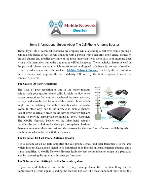
What is antenna booster? • A device used to amplify the signal received (by ratio) by the antenna before feeding to the television receiver. • A signal protection box that regulates television frequency signal.
Booster Block Diagram Antenna input Lo Detector Re-transmit Signal Detector Duplexer Directional coupler Receiver Input
Detecting Receivers • Allow secondary users in licensed bands if they can guarantee that they do not interfere with primary receivers. Ch. 3,4,5,6,7 Ch.5 Ch.9 Ch.3 shadower Ch.5 Ch.4 Ch.7 Ch.6
Detecting “Passive” Receivers • Legacy receivers must be able to function interference free. • All RF receivers leak local oscillator out of antenna. • Solution: Low cost sensors to detect leakage. Reverse LO leakage
TV Detector Vans • Used since 1920s
Cognisensor • Optimal to connect sensor directly between receiver and antenna. • Increases LO power coupled to sensor, reduces interference. • Allows sensor to reuse receive antenna for transmission. Cognisensor, close up Antenna input CR Duplexer cognisensor Transmitter Directional Coupler LO Detector Receiver Input
ANATOMY OF AN ANALOG TV SIGNAL example; channel 19 Lower Edge – 500.000 MHz Upper Edge – 506.000 MHz 0 amplitude Video Carrier center freq – 501.250 MHz Color Carrier center freq – 504.830 MHz Audio Carrier center freq – 505.750 MHz
ANATOMY OF A DIGITAL TV SIGNAL example; channel 19 Lower Edge – 500.000 MHz Upper Edge – 506.000 MHz 0 amplitude Video, Color and Audio Carrier Signals Are Scattered Throughout the Bandwidth at FULL Amplitude
Equal Frequency allocation of UHF TV in the UHF SPECTRUM
TV Booster Common Problems • No power • Intermittent signal • Light bars rolling up or down • Foggy pictures • Weak signal • Pictures color on and off • Sagging pictures