Download
1 / 40
400 likes | 607 Vues
Antennas 101 Part 1 Antenna Basics and SAFETY. DUKE CITY HAM FEST PRESENTATION BY CHUCK PALMER NM5F. A HDARC PRESENTATION. SAFETY – First – Always Stay away from power lines Don’t do antenna work at night or in inclement weather Know the limits and requirements of your supporting structure

E N D
Antennas 101Part 1Antenna BasicsandSAFETY DUKE CITY HAM FEST PRESENTATION BY CHUCK PALMER NM5F
A HDARC PRESENTATION • SAFETY – First – Always • Stay away from power lines • Don’t do antenna work at night or in inclement weather • Know the limits and requirements of your supporting structure • Use Common Sense
A HDARC PRESENTATION • Anything will work! However, • More efficient the antenna the performance envelope is expanded • More efficient the antenna the longer window to make QSOs • Primary Key in antennae is efficiency • More efficient the antenna the more enjoyment of Amateur Radio
A HDARC PRESENTATION • If you increase your antenna efficiency, you expand your performance envelope and you will be able to hear and WORK more stations providing more enjoyment of radio • If you increase only your transmit power, you expand your “transmit envelope” and can work those stations you can hear not to mention the ones that can hear you, but you can’t hear.
A HDARC PRESENTATION • How does the radio signal propagate from transmitter to receiver? • In several ways, depending on the frequency • Low freq (less than 3 Mhz) by ground wave (AM broadcast) • Short wave (3 -30 Mhz) travel 30 to 250 mi into the ionosphere where they are reflected back to earth. Several hops are possible for long distance . • VHF and up is point to point
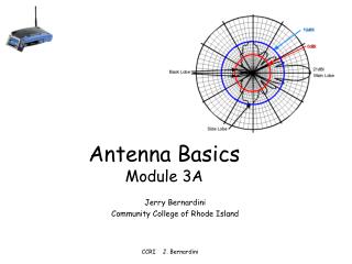
A HDARC PRESENTATION • Definitions • Isotropic Radiator – A theoretical antenna in free space that radiates equally well in all directions. • Gain – Increase in amplitude of a signal, measured in dB • Decibel (dB) – Logarithmic measurement of gain. • dBi – Gain measured in relation to an isotropic radiator
A HDARC PRESENTATION • Characteristics of Antennas • Polarization • Orientation of the driven element • Horizontal Directivity • Omni-directional VS. Directional • Vertical Directivity • Frequency Bandwidth • Effective Power Gain
A HDARC PRESENTATION • Effective Power Gain • Effective Isotropic Radiated Power (EIRP) • Isotropic antenna radiates equally in all directions • An antenna that radiates better in one direction than another, it would normally have “Gain” in this direction. The amount of gain would be the EIRP normally graduated in dB.
A HDARC PRESENTATION Definitions • dBd– Gain measured in relation to a dipole, dBd= dBi + 2.15. • Azimuth Pattern – Radiation pattern of the antenna when viewed from above. Directional or omni directional. • Elevation Pattern – Angle of maximum radiation in relation to the ground. Lower is better for DX. • Balun– For BALanced/UNbalanced. A device to force equal currents in coax.
A HDARC PRESENTATION • How Much Gain is a dB? • 0 dB = 1 • 1 dB = 1.26 • 2 dB = 1.58 • 3 dB = 1.99 • 4 dB = 2.51 • 5 dB = 3.16 • 6 dB = 3.98 = 1 S unit • 7 dB = 5.01 • 8 dB = 6.31 • 9 dB = 7.94 • 10 dB = 10
A HDARC PRESENTATION • Gain for Various Antenna Types • Dipole: 2.5 dBi • Yagi: 3 to 20 dBi • Corner Reflector: 4 to 10 dBi • Parabolic Dish: 10 to 30 dBi • Rule of thumb: the narrower the beam the higher the gain
A HDARC PRESENTATION • Transmission Lines • RG-58 (Always use the • RG-8/U best transmission • RG-8/x (Mini 8) line you can afford) • RG-213 • LMR400 • RG-59 • RG-6 • Ladder Line
A HDARC PRESENTATION • Three Rules for Coax • The longer the run, the higher the loss • Given similar materials, the larger the Coax the lower the losses (RG-8 vs. RG-58 • The higher the frequency the higher the loss ratio.
A HDARC PRESENTATION • Coax Connectors • SMA • BNC • UHF • N
A HDARC PRESENTATION • Dipole (the basic and some say best) • 2.15 dB gain over an Isotropic Radiator • Balanced design • Resonant on one band • Traps can be added to make it multi-band • Fan Dipole • Nominal 50 ohm impedance • Gain increases with height (true for all antennas) • Formula for calculating dipole length 468/F(MHz)
A HDARC PRESENTATION Dipole Cousins • Inverted V – Only needs one support. 5% shorter than a dipole. Takes up less space. • Off Center Fed Dipole – Feed point is 20-33% from one end. Feed point impedance is high and requires a 4-1 balun. • Windom – Similar to the OCFD. Fed at 34% from the end, it uses a single feed wire and can be resonant on more than one band. • Double Bazooka – Broad banded dipole made out of coax.
A HDARC PRESENTATION • Vertical Antennas • Mono band ¼ wavelength with ¼ wave counter-poise or radials or • Vertical Dipole that does not require radials. • Can be multi-band with traps. Requires ¼ wave radials for each band or many (60+) short radials. • Noisier than horizontal antennas • Easier to hide in antenna restricted areas (can be disguised as flagpole or be a single wire in a tree) • Gain is less than a dipole
A HDARC PRESENTATION • Summery: • Safety – First – Last - Always • Efficiency is the Key to a good antenna • Use good transmission line • Use good properly installed connectors • What is an Isotropic source – What is a Dipole source • Remember what dBi and dbd is • Polarization, Horizontal, Vertical Directivity, Bandwidth • Effective Radiated Power • What is “Gain?” How does a gain antenna work? • How to make a basic “dipole” antenna • Elevation is always good • Always use radials with a vertical antenna
Antennas 101Part 2Antenna TYPES AND SELECTION DUKE CITY HAM FEST PRESENTATION BY CHUCK PALMER NM5F
WHAT DOES IT ALL MEAN ? WELCOME TO THE REAL WORLD OF ANTENNAS !
Real World Basics You Should Be Aware Of Remember, the Isotropic antenna is a theoretical antenna exhibiting a perfect omni-directional pattern. Many antenna manufactures love to rate their antennas in dbi, which will always show a higher gain figure by 2.15 db. Real World gain figures are always expressed in dbd, referring to db referenced to a dipole. In the real world, the dipole reference is 0 db. Therefore, if you see an antenna having a gain of 3 dbi, it’s actual gain is 3 dbi – 2.15 db, or .85 dbd. Doesn’t look so good now, does it? Gain expressed in db are meaningless when not referenced to something.
THE ADVANTAGE OF DIRECTIONAL ANTENNAS • 0 dB = 1 • 1 dB = 1.26 • 2 dB = 1.58 • 3 dB = 1.99 • 4 dB = 2.51 • 5 dB = 3.16 Directional antennas exhibit gain, expressed in db and ERP (Effective Radiated Power) 3db is a power gain of 2. 100 watts into a reference dipole will exhibit an ERP of 100 watts (0db) 100 watts into an antenna with 3 dbd gain will exhibit an ERP of 200 watts. 6 dbd will become 400 watts, etc.
Something for nothing, right? • Not at all. • The directional antenna has the property of concentrating RF power in one direction, at the expense of the back and sides of the antenna. This is a real advantage, not only in transmitting in one direction, but rejecting interfering signals from the back and sides of the antenna. • This effect also aids the station you are talking to.
What To Consider When Selecting An Antenna • Frequency Range You Will Be Using • Size Limitations • Directional or Omni (Beam or Vertical) • Polarity (Horizontal or Vertical) • CC&R’s • Power • Proper mounting structure • Weather considerations • Safety, Safety, Safety!!
THERE IS AN ANTENNA FOR EVERY SITUATION AND BUDGET Wire antennas, such as dipoles, inverted V’s, long wires, G5RV’s Zepps, etc, are inexpensive and are effective in degrees. Verticals are especially good for working DX because of their low angle radiation pattern. Various beams, such as the Yagi – Uda, Cubical Quad, Hex Beam and Moxon provide superior gain and directivity when properly built and installed.
A HDARC PRESENTATION • Mini-beams work very well, with reduced gain figures and will get you on the air with a smaller, yet effective beam. • The Log Periodic is well suited when wide bandwidth along with modest gain is needed. • In reality, anything will radiate. So experimenting with antennas is great fun. You would be surprised what many resourceful hams have built and successfully used to get on the air!
A HDARC PRESENTATION Yagi Antennas • Multi Elements – Driven element, reflector and director(s) • Two to Ten or more elements • About 70Ω nominal impedance • Mono or Multiband • Three element tri-bander (20 - 15 - 10m) is the most common
A HDARC PRESENTATION Moxon • Invented by Les Moxon, G6XN • Variation of the Yagi – Uda • More compact than Yagi, slightly less gain (0.2dB) • Popular for Field Day and Portable use • Very high F/B ratio
A HDARC PRESENTATION • Log Periodic • LPDA – Log Periodic Dipole Array • Very broadband, an octave or more • Bigger and heavier than a Yagi • Multiple band with a single feedpoint • Alternating elements are phased 180° apart • Uses stubs for impedance matching • Example: Typical outdoor TV antenna
A HDARC PRESENTATION • Quad • Developed by Clarence C. Moore , W9LZX, at missionary radio station HCJB in Ecuador • Lightweight, made of wire usually • Usually two to four elements (2 element Quads are called “Cubical Quads” because of the cubical shape • Can be mono-band or multiband • Multiband is complex to adjust because of element interaction
A HDARC PRESENTATION Hex Beam • Small and light with low wind loading • Can be used on a lightweight tower with a small rotor • Less gain than a Yagi • Relatively poor F/B ratio as you move farther from the resonant frequency • Looks kind of odd but works well
A HDARC PRESENTATION • Beware of “GAIN CLAIMS” • Remember the difference between dBi and dBd, that is 2.15 dB • Research the theoretical gain of a full sized mono-band beam (Yagi for example) and compare the gain to the claim for a shortened trapped multi-band or other beam. • There are losses, the shortened multi bander cannot be the same or better than the full sized mono bander, just can’t be!
A HDARC PRESENTATION • Questions? • Sources: • ARRL Antenna Handbook – A must-have book, you can purchase a used copy for under $20.00 • www.cebik.com –Website of L.B. Cebik, W4RNL (SK). Must register, but it’s free. • Array of Light 3rd edition -Tom Schiller N6BT • Liberally lifted from Rob May NV5E • www.google.com is your friend.