GAS TURBINE CYCLES
GAS TURBINE CYCLES. Mohsin Mohd Sies Fakulti Kejuruteraan Mekanikal , Universiti Teknologi Malaysia. Objectives. Evaluate the performance of gas power cycles for which the working fluid remains a gas throughout the entire cycle.

GAS TURBINE CYCLES
E N D
Presentation Transcript
GAS TURBINE CYCLES MohsinMohdSies FakultiKejuruteraanMekanikal, UniversitiTeknologi Malaysia
Objectives • Evaluate the performance of gas power cycles for which the working fluid remains a gas throughout the entire cycle. • Develop simplifying assumptions applicable to gas power cycles. • Analyze both closed and open gas power cycles. • Solve problems based on the Brayton cycle; the Brayton cycle with regeneration; and the Brayton cycle with intercooling, reheating, and regeneration.
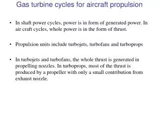
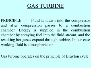
Introduction A gas turbine is an engine that discharges a fast moving jet of fluid to generate thrust in accordance with Newton's third law of motion. This broad definition of jet engines includes turbojets, turbofans, rockets and ramjets and water jets, but in common usage, the term generally refers to a gas turbine used to produce a jet of high speed exhaust gases for special propulsive purposes. F-15 Eagle engine is tested at Robins Air Force Base, Georgia, USA F-15 Eagle is powered by two Pratt & Whitney F100 axial-flow turbofan engines
So why does the M-1 tank use a 1,500 horsepower gas turbine engine instead of a diesel engine? • Advantages of Gas Turbines • Great power-to-weight ratio compared to reciprocating engines. i.e. the amount of power you get out of the engine compared to the weight of the engine itself is very good. • Smaller than their reciprocating counterparts of the same power • Disadvantages of Jet Engines • Compared to a reciprocating engine of the same size, gas turbines are expensive - because of the high spin and operating temperatures, designing and manufacturing gas turbines is a tough problem • Gas turbines use more fuel when they are idling, and they prefer a constant rather than a fluctuating load.
Gas Turbine Applications • Aircraft propulsion system • Electric power generation • Marine vehicle propulsion • Combined-cycle power plant (with steam power plant) • Tanks
Main Components of Gas Turbine Power Plant • 1. Compressor • The compressor sucks in air form the atmosphere and compresses it to pressures in the range of 15 to 20 bars. • The compressor consists of a number of rows of blades mounted on a shaft. • The shaft is connected and rotates along with the main gas turbine.
Main Components of Gas Turbine Power Plant • 2. Combustor • This is an annular chamber where the fuel burns and is similar to the furnace in a boiler. • The hot gases in the range of 1400 to 1500 °C leave the chamber with high energy levels. • The chamber and the subsequent sections are made of special alloys and designs that can withstand this high temperature
Main Components of Gas Turbine Power Plant • 3. Turbine • The turbine does the main work of energy conversion. • The turbine portion also consists of rows of blades fixed to the shaft. The kinetic energy of the hot gases impacting on the blades rotates the blades and the shaft. • The gas temperature leaving the Turbine is in the range of 500 to 550 °C.
How Does a Gas Turbine Work? • Fresh air at ambient conditions is drawn into the compressor, its temperature and pressure are raised. • The high-pressure air proceeds into the combustion chamber, the fuel is burned at constant pressure. • The resulting high-temperature gases then enter the turbine and expand to the atmospheric pressure while producing power. • The exhaust gases leaving the turbine are thrown out (not re-circulated), causing the cycle to be classified as an open cycle.
Various engine types: Turbofan, Propjet, Ramjet, Scramjet, Rocket A turboprop engine. A ramjet engine.
Modifications to Turbojet Engines The first airplanes built were all propeller-driven, with propellers powered by piston engines Both propeller-driven engines and jet-propulsion-driven engines have their own strengths and limitations, and several attempts have been made to combine the desirable characteristics of both in one engine. Two such modifications are the propjet engineand the turbofan engine. The most widely used engine in aircraft propulsion is the turbofan (or fanjet) engine wherein a large fan driven by the turbine forces a considerable amount of air through a duct (cowl) surrounding the engine. A turbofan engine.
Brayton Cycle: Ideal Cycle for Gas-Turbine Engines Gas turbines usually operate on an open cycle (Fig. 9–29). Air at ambient conditions is drawn into the compressor, where its temperature and pressure are raised. The high pressure air proceeds into the combustion chamber, where the fuel is burned at constant pressure. The high-temperature gases then enter the turbine where they expand to atmospheric pressure while producing power output. Some of the output power is used to drive the compressor. The exhaust gases leaving the turbine are thrown out (not re-circulated), causing the cycle to be classified as an open cycle.
Closed Cycle Model The open gas-turbine cycle can be modelled as a closed cycle, using the air-standard assumptions (Fig. 9–30). The compression and expansion processes remain the same, but the combustion process is replaced by a constant-pressure heat addition process from an external source. The exhaust process is replaced by a constant-pressure heat rejection process to the ambient air.
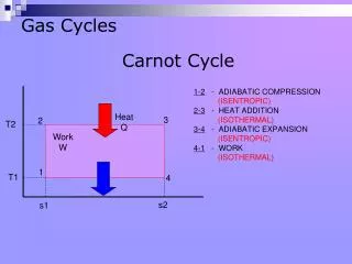
The Brayton Cycle The ideal cycle that the working fluid undergoes in the closed loop is the Brayton cycle. It is made up of four internally reversible processes: 1-2 Isentropic compression; 2-3 Constant-pressure heat addition; 3-4 Isentropic expansion; 4-1 Constant-pressure heat rejection. The T-s and P-v diagrams of an ideal Brayton cycle are shown in Fig. 9–31. Note: All four processes of the Brayton cycle are executed in steady-flow devices thus, they should be analyzed as steady-flow processes.
Review SSSF Energy Equation Relationship of P, v, T between two states under polytropic process for ideal gases For an isentropic process Specific Heat Ratio
AIR-STANDARD ASSUMPTIONS • Air-standard assumptions: • The working fluid is air, which continuously circulates in a closed loop and always behaves as an ideal gas. • All the processes that make up the cycle are internally reversible. • The combustion process is replaced by a heat-addition process from an external source. • The exhaust process is replaced by a heat-rejection process that restores the working fluid to its initial state. The combustion process is replaced by a heat-addition process in ideal cycles. Cold-air-standard assumptions: When the working fluid is considered to be air with constant specific heats at room temperature(25°C). Air-standard cycle: A cycle for which the air-standard assumptions are applicable.
Thermal Efficiency The energy balance for a steady-flow process can be expressed, on a unit–mass basis, as The heat transfers to and from the working fluid are: The thermal efficiency of the ideal Brayton cycle, Constant specific heats is the pressure ratio. where
A Practical Consideration • To take into consideration the large change of temperature throughout the cycle and the change of air into combustion gases while still maintaining a simple ideal gas analysis, we usually treat the working fluid as • Air inside the compressor, with Cpand k of air, and • Combustion gas inside the combustor and turbine, with different values of Cpand k.
Problem Ideal and Actual Gas-Turbine (Brayton) Cycles • 9–73 • A simple Brayton cycle using air as the working fluid has a pressure ratio of 8. The minimum and maximum temperatures in the cycle are 310 K and 1160 K, respectively. Assuming an isentropic efficiency of 75 percent for the compressor and 82 percent for the turbine, determine: • the air temperature at the turbine exit, • the net work output, and • the thermal efficiency. • Use air-standard, ideal gas, constant specific heats assumptions. 9–77 A stationary gas-turbine power plant operates on a simple ideal Brayton cycle with air as the working fluid. The air enters the compressor at 95 kPa and 290 K and the turbine at 760 kPa and 1100 K. Heat is transferred to air at a rate of 35,000 kJ/s. Determine the power delivered by this plant:
Parameters Affecting Thermal Efficiency The thermal efficiency of an ideal Brayton cycle depends on the pressure ratio, rp of the gas turbine and the specific heat ratio, k of the working fluid. The thermal efficiency increases with both of these parameters, which is also the case for actual gas turbines. A plot of thermal efficiency versus the pressure ratio is shown in Fig. 9–32, for the case of k =1.4.
The highest temperature in the cycle is limited by the maximum temperature that the turbine blades can withstand. This also limits the pressure ratios that can be used in the cycle. Tmax limited by materials, Tmin limited by environment The fraction of the turbine work used to drive the compressor is called the back work ratio.
Back Work Ratio • BWR is defined as the ratio of compressor work to the turbine work • The BWR in gas turbine power plant is very high, normally one-half of turbine work output is used to drive the compressor • Thus requires a larger turbine
Improvements of Gas Turbine’s Performance The early gas turbines (1940s to 1959s) found only limited use despite their versatility and their ability to burn a variety of fuels, because its thermal efficiency was only about 17%. Efforts to improve the cycle efficiency are concentrated in three areas: • Increasing the turbine inlet (or firing) temperatures. • The turbine inlet temperatures have increased steadily from about 540°C (1000°F) in the 1940s to 1425°C (2600°F) and even higher today. • Increasing the efficiencies of turbo-machinery components (turbines, compressors). • The advent of computers and advanced techniques for computer-aided design made it possible to design these components aerodynamically with minimal losses. • Adding modifications to the basic cycle (intercooling, regeneration or recuperation, and reheating). • The simple-cycle efficiencies of early gas turbines were practically doubled by incorporating intercooling, regeneration (or recuperation), and reheating.
Actual Gas-Turbine Cycles Some pressure drop occurs during the heat-addition and heat rejection processes. The actual work input to the compressor is more, and the actual work output from the turbine is less, because of irreversibilities. Deviation of actual compressor and turbine behavior from the idealized isentropic behavior can be accounted for by utilizing isentropic efficiencies of the turbine and compressor. Turbine: Compressor:
Problem Class Exercise Ideal and Actual Gas-Turbine (Brayton) Cycles • 9–78 • Air enters the compressor of a gas-turbine engine at 300 K and 100 kPa, where it is compressed to 700 kPa and 580 K. Heat is transferred to air in the amount of 950 kJ/kg before it enters the turbine. • For a turbine efficiency of 86 percent, determine: • (a) the fraction of turbine work output used to drive the compressor, • (b) the thermal efficiency.
Brayton Cycle With Regeneration Temperature of the exhaust gas leaving the turbine is higher than the temperature of the air leaving the compressor. The air leaving the compressor can be heated by the hot exhaust gases in a counter-flow heat exchanger (a regenerator or recuperator) – a process called regeneration (Fig. 9-38 & Fig. 9-39). The thermal efficiency of the Brayton cycle increases due to regeneration since less fuel is used for the same work output. Note: The use of a regenerator is recommended only when the turbine exhaust temperature is higher than the compressor exit temperature.
Effectiveness of the Regenerator Assuming the regenerator is well insulated and changes in kinetic and potential energies are negligible, the actual and maximum heat transfers from the exhaust gases to the air can be expressed as Effectiveness of the regenerator, Effectiveness under cold-air standard assumptions, = Thermal Ratio Thermal ratio Thermal efficiency under cold-air standard assumptions,
Problem Brayton Cycles with Regeneration • 9–91 • The 7FA gas turbine manufactured by General Electric is reported to have an efficiency of 35.9 percent in the simple-cycle mode and to produce 159 MW of net power. The pressure ratio is 14.7 and the turbine inlet temperature is 1288°C. The mass flow rate through the turbine is 1,536,000 kg/h. • Taking the ambient conditions to be 20°C and 100 kPa, determine: • (a) the isentropic efficiencyof the turbine and the compressor, • the thermal efficiency of this gas turbine if a regenerator with an effectiveness of 80 percent is added. • Assume constant specific heats at 300 K.
Problem Brayton Cycles with Regeneration • 9–96 • A Brayton cycle with regeneration using air as the working fluid has a pressure ratio of 7. The minimum and maximum temperatures in the cycle are 310 and 1150 K respectively. • Assuming an isentropic efficiency of 75 percent for the compressor and 82 percent for the turbine and an effectiveness of 65 percent for the regenerator, determine: • (a) the air temperature at the turbine exit, • (b) the net work output, and • (c) the thermal efficiency. • Answers: (a) 783 K, (b) 108.1 kJ/kg, (c) 22.5 percent
Brayton Cycle With Intercooling, Reheating, & Regeneration The net work output of a gas-turbine cycle can be increased by either: a) decreasing the compressor work, or b) increasing the turbine work, or c) both. The compressor work input can be decreased by carrying out the compression process in stages and cooling the gas in between (Fig. 9-42), using multistage compression with intercooling. The work output of a turbine can be increased by expanding the gas in stages and reheating it in between, utilizing a multistage expansion with reheating.
Physical arrangement of an ideal two-stage gas-turbine cycle with intercooling, reheating, and regeneration is shown in Fig. 9-43.
Problem Brayton Cycle with Intercooling, Reheating, and Regeneration • 9–108 • Consider an ideal gas-turbine cyclewith two stages of compression and two stages of expansion. The pressure ratio across each stage of the compressor and turbine is 3. The air enters each stage of the compressor at 300 K and each stage of the turbine at 1200 K. Determine: • the back work ratio, and • the thermal efficiency of the cycle • assuming: • no regenerator is used, and • a regenerator with 75 percent effectiveness is used.
Conditions for Best Performance The work input to a two-stage compressor is minimized when equal pressure ratios are maintained across each stage. This procedure also maximizes the turbine work output. Thus, for best performance we have, Intercooling and reheating always decreases thermal efficiency unless are accompanied by regeneration. Therefore, in gas turbine power plants, intercooling and reheating are always used in conjunction with regeneration.
Problem Brayton Cycle with Intercooling, Reheating, and Regeneration 9–110 Consider a regenerative gas-turbine power plant with two stages of compression and two stages of expansion. The overall pressure ratio of the cycle is 9. The air enters each stage of the compressor at 300 K and each stage of the turbine at 1200 K. Determine the minimum mass flow rate of air needed to develop net power output of 110 MW. Answer: 250 kg/s. (with variable specific heat assumption)