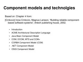
Based on: Chapter 4 from:
Component models and technolgies. Based on: Chapter 4 from: [Crnkovic] Ivica Crnkovic, Magnus Larsson, “Building reliable component-based software systems”, Artech publishing house, 2002. Introduction ACME Architectural Description Language Java Bean Component Model COM, DCOM, MTS and COM+

Based on: Chapter 4 from:
E N D
Presentation Transcript
Component models and technolgies • Based on: Chapter 4 from: • [Crnkovic] Ivica Crnkovic, Magnus Larsson, “Building reliable component-based software systems”, Artech publishing house, 2002. • Introduction • ACME Architectural Description Language • Java Bean Component Model • COM, DCOM, MTS and COM+ • CORBA Component Model (CCM) • .NET Component Model • OSGI Component Model
Review: Basic CBSE concepts Fig.1.1. from [Crnkovic]
Review: Component execution Platform Services: allow components written according to the model to communicate; locating, linking, replacing components Component Component Component Component platform (component framework) Operating System Middleware Horizontal Services: application-independent services used by different components. Concurrency, security, transaction management, Resource management Hardware
Major steps in CBD Lifecycle Table.4.1. from [Crnkovic]
Review: What is a component? • Szyperski, Component Oriented Programming: • “A software component is a unit of composition with contractually specified interfaces and explicit context dependencies only. A software component can be deployed independently and is subject to composition by third-parties.” Bass, Clements, Kazman, Software Architecture in Practice: “The software architecture of a program is the structure or structures of the system, which comprise software components and connectors, the externally visible properties of these components and the relationships among them”
Industrial component technologies vs Architectural components • Industrial component technologies: • focus on the last phases of the CBD life cycle (implementation, deployment, and execution) • focus on practical problems and are described in technical terms, thus providing many implementation details and making it difficult for users to understand concepts and principles. • Available documentation is either oriented toward decision makers and provides mostly marketing arguments, or it is oriented toward programmers or tool implementers and includes pieces of code and complex API specifications • Architectural components: • Defines high-level concepts and principles • Focus on early stages (design)
Industrial component technologies vs Architectural components (cont) • Comparing component technologies and Architectural components: • It is useful because they share the component concept and their scope is complementary. • difficult because they do not address the same problems and they are not described at the same level of abstraction. • The goal of this chapter: • is to describe component technology in the same terms as architectural components and at the same abstraction level. • Identifies the component model underlying each component technology. This allows us to identify similarities and differences
Comparison methodology (1) • Compared aspects: steps of component life cycle Table.4.1. from [Crnkovic]
Comparison methodology (2) • Concepts (terminology): from ADLs – common reference Fig.4.1 from [Crnkovic]
Architectural components and ADL’s • “The software architecture of a program is the structure or structures of the system, which comprise software components and connectors, the externally visible properties of these components and the relationships among them” • Architecture Description Languages (ADL’s) must be able to describe certain views of the system • IEEE 1471-2000-2007: “Recomended Practice for Architectural Description of Software-Intensive Systems” • Nenad Medvidovic and Richard Taylor. A Classification and Comparison Framework for Software Architecture Description Languages.
ADL example: ACME • Goal of ACME: design and evaluation of software architectures • Tools: textual and graphic notation • ACME Concepts: • Components and Ports • Connectors and Roles • Systems and Attachments • Representations and Bindings • Properties, Constraints, Types and Styles
ACME ADL: Components and Ports • Components • Represent the computational elements and data stores of a system. • There are no restrictions on the size of a component. • Ports • The interface of a component (its external view) is described as a set of ports • Ports are the points of interaction between a component and its environment. Fig.4.2.a from [Crnkovic]
ACME ADL: Connectors and roles • Connectors • Represent interactions between components • Like components, connectors can be of arbitrary complexity • This notion makes it possible to represent, in a unified way, simple concepts such as a method call as well as complex and abstract connections such as an SQL connection between a client and a database server. • The interface of a connectoris defined as a set of roles • A role is to a connector what a port is to a component, that is, its interaction points. • For instance, a method call is a connector with two roles, the caller and the callee; a pipe has a writer and a reader; an event channel has an emitter and a receiver, and so forth. Fig.4.2.b from [Crnkovic]
ACME ADL: Systems and attachements • The structure of a system is specified by a set of components, a set of connectors, and a set of attachments. • Attachment • Links a component port to a connector role. • Connections between components are thusmodeled as a component–-port-–role-–connector-–role-–component sequence. Fig.4.2.c from [Crnkovic]
ACME ADL: Representations and Bindings • To support top-down design, a refinement feature is needed • One or more componentrepresentations can be associated with a component interface. • A component representation is made of a system and a set of bindings. Each binding links an internal port to an external port. A component can thus be decomposed hierarchically. Fig.4.3. from [Crnkovic]
ACME ADL: Properties, Constraints, Types and Styles • The concepts introduced can be used to describe the structural aspect of software architecture. • To improve the description of components, connectors, and systems, each ADL offers additional information to define, for instance, component behavior, protocols of interaction, and functional and extrafunctional properties.
ACMe ADL: Discussion • Acme defines a relatively small set of clearly identified concepts commonly found in other ADLs and can be considered as a typical ADL. • Acme does not contain all of the features found in all ADLs, but its generality and focus on structural aspects makes it particularly interesting in a comparison with typical industrial component models. • industrial component models concentrate on a subset of the concepts described above and largely ignore advanced features such as behavior specification. • Finally Acme, in the same way as other ADLs, emphasizes the notation and design of new systems but does not provide substantial help for implementation software or dealing with existing pieces of code
Component models and technologies • Compared in this chapter: • Java Bean Component Model • COM, DCOM, MTS and COM+ • CORBA Component Model (CCM) • .NET Component Model • OSGI Component Model • Comparison methodology: • Common reference: architectural component concepts from ACME ADL • Discussed/Compared aspects: • Interface • Assembly • Implementation • Life cycle • Framework support
Java Beans Component Model • The JavaBeans component model was proposed by Sun in 1997, as the first integration of the notion of a component on top of the Java language • Sun later released a second distinct component model, namely, Enterprise JavaBeans (EJB). These two models are fairly distinct and should not be confused because their names are misleading. • Discussion: • Key Features • Interface of a Component • Implementation of a Component • Components Assembly • Packaging and Deployment
JavaBeans - Key features • "A Java Bean is a reusable software component that can be manipulated visually in a builder tool”. • The Java Bean was designed for the construction of graphical user interface (GUI). • An interesting aspect of this component model is the importance given to the various contexts in which a component can be considered: • Explicitly tailored to interact in two different contexts: • At composition time, within the builder tool. • At execution time, with the runtime environment. • Bean Box
JavaBeans - Interface of a component • A bean can be described from an external view as a set of ports though this terminology is not used in JavaBeans • This model defines four types of ports: • methods, • properties, • event sources and • event sinks called listeners. Fig.4.4. from [Crnkovic]
JavaBeans - Implementation of a component • Most bean components are implemented by a simple Java object, the object being encapsulated in the component • Mapping between object methods and component ports is implicit with naming conventions • There are also more sophisticated implementations possible. • Wrapping a legacy object. • Multiple-objects implementation. • Dependency on traditional entities. Fig.4.5. from [Crnkovic]
JavaBeans - Components Assembly • Assembly is one of the key features of Java Bean though no not specific solution is provided. • Different ways of assembling components are supplied: • “visual builders, allowing the direct pluggingtogether of JavaBeans (BeanBox) • other builders may enable users to convenientlywrite Java classes that interact with and control a set of beans. • Other buildersmay provide a simple scripting language to allow easy high-level scripting of asetofbeans Fig.4.6. from [Crnkovic]
JavaBeans - Packaging and Deployment • JavaBeansdefineamodelforpackagingcomponentsintoarchives.Whenthearchive is loaded into a builder tool, all packaged beans will be added to thedirectoryofavailablecomponents. • Packagingisrequiredinpracticebecausemostbeancomponentsdependon resources (e.g., icons and configuration files) and on other Java classes. Toavoid duplication of items shared by different beans, it is therefore better topackage all of these items together. • To handle packaging issues, the JavaBeansdefinition includes the definition of dependency relationships between thepackageitems. • Each package item can be marked "Design Only", so that they can be removed in a final application. • The customization code can be more complex than the component itself!
Component models and technologies • Compared in this chapter: • Java Bean Component Model • COM, DCOM, MTS and COM+ • CORBA Component Model (CCM) • .NET Component Model • OSGI Component Model • Comparison methodology: • Common reference: architectural component concepts from ACME ADL • Discussed/Compared aspects: • Interface • Assembly • Implementation • Life cycle • Framework support
COM, DCOM, MTS, COM+ • These technologies come from Microsoft. • COM (1995) is typical of earlyattempts to increase program independence and allow programming languageheterogeneity, but for C/C++ like languages, in a centralized context,and on Windows platforms. COM relies on binary interoperability conventionsand on interfaces. • DCOM extends COM with distribution • MTSextends DCOM with persistency and transaction services. • Together COM, DCOM, MTS theyconstituteCOM+ • Discussion: • Interfaces and Assembly • Implementation • Framework • Lifecycle
COM+ - Interfaces and Assembly • A COM interface is seen as a C++ virtual class and takes the form of a list of data and function declarations without associated code. • COM doesnot provide an assembly language; it instead provides a simple protocol thatCOM objects can use to dynamically discover or create objects and interfaces.All interfaces are descendants of the IUnknown interface, which definesthebasicfunctions:QueryInterface,AddRef,andRelease. Fig.4.7. from [Crnkovic]
COM+ - Component Implementation • A COM object is a piece of binary code, written in any programming language, as long as the compiler generates code following the binary interoperability convention.
COM+ - Framework • COM Framework consists of: • Standard interfaces (IUnknown, IDispatch, etc) • A simple run-time : interprets, together with the runtime DLL, the calls for creating COM objects, returning interface handles, and managing the reference count for releasing objects • DCOM extends COM with distribution • Interfaces are defined in the MIDL language
COM+ - Lifecycle • COM, and COM+ are strictly execution time and binary component models. • No lifecycle issues are explicitly supported.
Component models and technologies • Compared in this chapter: • Java Bean Component Model • COM, DCOM, MTS and COM+ • CORBA Component Model (CCM) • .NET Component Model • OSGI Component Model • Comparison methodology: • Common reference: architectural component concepts from ACME ADL • Discussed/Compared aspects: • Interface • Assembly • Implementation • Life cycle • Framework support
CORBA Component Model (CCM) • Component specification from OMG • Very complex • Generalizes experiences ofCORBA, EJB, JavaBeans • One of the advantages of CCM is its effort to “integrate” many of thefacetsinvolvedinsoftwareengineering.Asaconsequence,asoftwareapplicationis described in different formalisms along two dimensions: the timedimension (the life cycle, from design to deployment) and the abstractdimension (from abstractions to implementation). • Discussion: • Interface and Assembly • Framework : The Container Approach • Lifecycle
CCM - Interfaces • A component interface is made of ports divided into: • Facets • Receptacles • Event sources • Event sinks • CCM considers ports as named and typed variables (most models consideronlyinterfaces,i.e.,atype),thusdifferentfacetsofthesamecomponentcan have the same type. Components are typed and can inheritfromothercomponents(i.e.,itinheritsitsinterface) Fig.4.8. from [Crnkovic]
CCM - Homes • Homes are component factories that manage a component instance lifecycle: creation, initialization, destruction, and retrieval of (persistent) componentinstances. • Homes are also typed and can inherit from other hometypes. A home type can manage only one component type, but a componenttype can have different home types. • Homes are defined independently fromcomponents, which allow component life-cycle management to be changedwithoutchangingthecomponentdefinition.
CCM - Assemblies • CCMsimplydefinestheconceptofconnectionas“anobjectreference”;thusCCM, like all other industrial component models, does not provide a connectorconcept. Nevertheless, components are connected by linking facets toreceptacles and event sources to event sinks. Connections are binaries andoriented,butthesameportcanhandlemultipleconnections. • Connections can be explicitly described (in the assembly descriptor, anXML file) and established by the CCM framework at initialization. A componentassembly describes the initial configuration of the application (i.e.,whichcomponentsmakeuptheassembly),howthosecomponentsarepartitioned, and how they are connected to each other. The assembly does notaddressarchitectureevolutionduringexecution
CCM – Component Implementation • The implementation of a component is a set of segments or executors. Segmentsare executable code written in any programming language, implementingat least one port. Segments are loaded only when required. No(segment) composition operators are defined. Nothing prevents a segmentfrom calling conventional programs; conversely, the concept of “equivalentinterface” was defined to turn a program into a component and to make acomponentappearasaclassicprogram. • Because implementation is always a set of executable code, the CCMmodel is not hierarchical. The same applies to homes which are directlyboundtoexecutors. • CCM proposes a Component Implementation Definition Language(CIDL) that describes the segments, the associated home executor, the typeof storage, and the class of container. Differentimplementationscanbeassociatedwiththesame(abstract)component
CCM - Framework: the container approach Fig.4.9. from [Crnkovic]
CCM - Framework: the container approach • Services can be made available to components without having to change that component’s source code. • Like EJB, CORBA components use a container to implement componentaccess to system services using common design patterns gleaned fromexperience in building business applications using object technology and CORBAservices. • Containersaredefinedin terms of how they use the underlyingCORBA infrastructure and thus are capable of handling services liketransactions, security, events, persistence, lifecycle services, etc. • Componentsare free to use CORBA services directly (component-managed service), but CCM emphasizes container-managed service (i.e., the container managing services automatically); the component code itself ignores the associated services. To do so, the container intercepts communications between components and calls, if needed, framework services. I
CCM - Lifecycle • CCM is the best effort to date: • To gather the advances made in different fields, • To include a wide spectrum of lifecycle activities, while still claiming efficiency and heterogeneity capabilities, • However, the whole does not provide the feeling of being as “simple” as claimed.
Component models and technologies • Compared in this chapter: • Java Bean Component Model • COM, DCOM, MTS and COM+ • CORBA Component Model (CCM) • .NET Component Model • OSGI Component Model • Comparison methodology: • Common reference: architectural component concepts from ACME ADL • Discussed/Compared aspects: • Interface • Assembly • Implementation • Life cycle • Framework support
.NET Component Model • .NET,the latest component model from Microsoft, represents a discontinuity —it no longer relies on COM, because binary interoperability is too limited. .NET relies instead on language interoperability and introspection. • To do so, .NET defines an internal language Microsoft Intermediate Language (MSIL), which is very similar to Java Byte Code and its interpreter with introspection capabilities: the Common Language Runtime (CLR), which is very similar to a Java VirtualMachine. • Discussion: • Interfaces and Assembly • Implementation • Framework • Lifecycle
.NET - Interfaces and Assembly • programming language approach for component programming. • The program contains the information related to the relationships with other “components”, and that the compiler is responsible for generating the information needed at execution. This (proprietary)approach contrasts with the Object Management Group (OMG) (open)approach where separate formalisms (and files) are used to indicatecomponent-related information, with languages and compilers beingunchanged. • What most resembles a component is an assembly. The manifest is thecomponent descriptor. It gathers in a single place all information about anassembly: exported and imported methods and events, code, metadata, andresources. • The compiler not only produces MSIL byte code but also generates,in the manifest, the interface description of the component (calledassembly), in the form of a list of import and export types. There is noexplicit concept of connection but rather the traditional list of imported andexported resources. .NET relies on a specific dynamic linker to realize theconnections,duringexecution,betweentheprovidedandrequiredresources.
.NET – Component Implementation • A component (assembly) is made of modules, which are traditional executable files (DLL). • Modules cannot be assemblies, thus the .NET model is not hierarchical. Fig.4.10. from [Crnkovic]
.NET - Framework • .NET relies on the traditional programming approach : the framework is seen as the language run-time support. • Extrafunctional aspects: distribution, security, confidentiality, versioncontrol.
.NET - Lifecycle • Visibility control: Assemblies (and their modules) are local to an application, and thus different DLLs with same name can run simultaneously. • Each assembly has a versioning information about itself and about the assemblies it depends on. • Version control is delegated to the dynamic loader, which selects the “right” version. • Significantly improve the application packaging and deployment. • Early lifecycles phases do not seem to have received much attention.
Component models and technologies • Compared in this chapter: • Java Bean Component Model • COM, DCOM, MTS and COM+ • CORBA Component Model (CCM) • .NET Component Model • OSGI Component Model • Comparison methodology: • Common reference: architectural component concepts from ACME ADL • Discussed/Compared aspects: • Interface • Assembly • Implementation • Life cycle • Framework support
OSGI Component Model • The OSGI was founded in 1999 with the mission of creating “open specificationsfor the delivery of multiple services over wide area networks to localnetworks and devices” • The OSGI emphasis is on a lightweight frameworkthat can be executed in low-memory devices. Actually, the OSGI targetsproducts such as set-top boxes, cable modems, routers, consumerelectronics, and so on. • The OSGI relies on Java to ensure portability on differenthardware. An important characteristic of this technology is that it hasbeentailoredtosupportdynamicevolutionofthesystemarchitecture.Componentscan be downloaded, updated, and removed dynamically, withouteven stopping the system. Moreover, the OSGI allows for remote administrationof the system via the network. • Discussion: • Components • Interface of a Bundle Component • Assembly of Bundle Components • Implementation of a Bundle Component
OSGI Components • The OSGI is based on two main concepts that can be interpreted as components:bundles and services. • “”Developers should design an application asa set of bundles that contain services, with each service implementing a segmentof the overall functionality. These bundles are then downloaded on demand” • Whilesomeauthorsdefinecomponentsasaunitofcompositionandasa unit of deployment, these two concepts can be distinguished in the OSGI.Aservice is a unit of composition; asystem is a set of cooperating services thatare connected. A bundle is a unit of deployment that groups a set of servicesthat can be deployed as a unit.
OSGI Bundle Components • A bundle packages a set of software entities that collectively form a piece ofsoftware. These entities may depend on entities packaged in other bundles,therefore creating dependencies between bundles. The OSGI manages thesedependencies. • A bundle use three kinds of ports to express its interactions with • Traditional technology • Other components • Bundlesmanagedynamicconnectionsbetweenservices.Atanytime, and for any reason, a bundle may display or remove a service interface. Similarly,atanytime,andforanyreason,abundlemayrequireorreleasetheuse of a service interface. Service interfaces can therefore be attached anddetacheddynamically • The run-time environment • Bundles may listen to events published by the framework such as the insertion of a new component in a system.
OSGI - Interface of a bundle component Fig.4.11. from [Crnkovic]