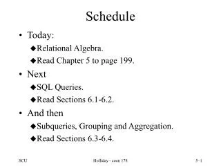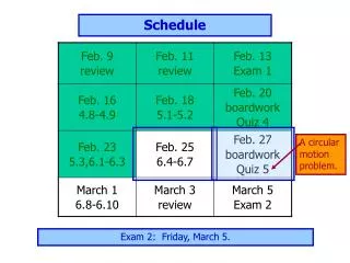
Preparation Schedule
Preparation Schedule. Subsystems Peer Reviews ACD January 7-8, 2003 CAL March 17-18, 2003 Elec/DAQ/PWR/Flt SW March 19-20, 2003 TKR March 24-25, 2003 Mech March 26-27, 2003 I&T March 28, 2003 Walk Through Review

Preparation Schedule
E N D
Presentation Transcript
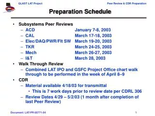
Preparation Schedule • Subsystems Peer Reviews • ACD January 7-8, 2003 • CAL March 17-18, 2003 • Elec/DAQ/PWR/Flt SW March 19-20, 2003 • TKR March 24-25, 2003 • Mech March 26-27, 2003 • I&T March 28, 2003 • Walk Through Review • Combined LAT IPO and GSFC Project Office chart walk through to be performed in the week of April 8–9 • CDR • Material available 4/18/03 for transmittal • This is 7 work days prior to review date per CDRL 306 • Review Dates 4/29 – 5/2/03 (1 month after completion of last Peer Review)
GSFC CDR Guideline • Paragraph 4.3 from the GSFC System Review Office Guideline
Entrance & Exit Criteria Design Status • Demonstrate evolution & heritage of “Final Design” • Demonstrate compliance of system performance • Closure of Actions from PDR & DPDR • Complete ICDs • Final implementation plans • EM • Prototype • Flight Units • Spares • Complete design analysis Fabrication Status • Qualification/Environmental Test Plan and Flow • Ground Operations • Control methods for all safety hazards identified • FMEA • Worst case analysis • Fracture control • Shipping environment and mode of transportation
CDR Check List • PDR – CDR Check List Comparison (reference GSFC SRO Checklist)
Breakdown of the CDR Check List for each Subsystem Check list is designed to provide a quick look of the project readiness for CDR
Preparation Examples • ACD has provided a website of their CDR preparation status • I encourage everyone to view posted material, including the CDR Dry Run charts http://lhea-glast.gsfc.nasa.gov/acd/cdr/index.html • The following slides are examples for each Check List category presented in the ACD charts
Closure of Action Items • Identified action items from PDR and DPDR • Show status and closure of NASA GSFC action items Identify the action requested AI# 2. Perform light yield tests and muon detection efficiency measurement of the final optical system (scintillator tiles; and fiber ribbons, connector, clear fibers, and photomultiplier tubes). Complete – results are similar to those shown in January: with two phototubes, 0.9997 efficiency is met; with one phototube, efficiency is ~ 0.999 Light output of Fermilab tiles is good. Light losses in the optical connector and clear fibers were higher than expected. Design improvements were made to compensate for these losses. LAT-TD-00843-D1, Design Qualification Tests for ACD TDA and Phototubes Show results
Design Specification • Science/technical objectives and technical budgets • Requirements & specifications metrics and flow down • All TBX (TBD, TBA, TBS, etc…) should be removed or addressed • Drawing metrics • Number and percent complete of major assemblies and critical component drawings • Plans for completing the remaining drawings Identify key requirements
Key Technical Budgets • Identified technical budgets, it’s allocation from LAT System, changes since PDR • Show allocation flow down within the subsystem Technical Resources • ACD Mass • Allocation 235 kg • ACD detailed estimate 270 kg (15% over PDR allocation. LAT has been notified, CR is being submitted) • ACD Power • Allocation 31 W (conditioned) • ACD detailed estimate 14 W max • Thermal Interface (max dissipation across ASD-LAT interface) • Dissipation Allocation 16 W • Dissipation Estimate <14 W Show break down of allocation within subsystem
Interface Control Document • ICD and IDD are completed and signed • Identify major trades to accommodate design • Remaining open issues should have closure plan • 24 identical robust circular connectors (38999, series 2) • 2 circular housekeeping connectors (38999, series 2) • Parts, pin outs, signal def, grounding all defined in ICD Show interfaces • DATA Products • Channel specific charged • particle VETOs • VETO hit maps • PHAs • Diagnostics • Housekeeping (thermistor • output, voltage monitor • output, direct to AEM)
Analysis/Modeling/EM Reports • Identify analysis and modeling performed since PDR • What are the impacts due to spacecraft/bus interface • Highlight impact to analysis due to design change • Highlight impact to design due to modeling change • Provide example of EM testing • Identify objective and results Example from ACD Subject of the test - Fermilab made TDA prototypes (T1 and T2) equipped with clear fiber extensions and fiber-to-fiber connectors (made by GSFC) M1 S1 S2 T1 T2 S3 M2 Efficiency measurement setup: M1, M2 - hardware trigger scintillators S1, S2, S3 - software trigger scintillators T1, and T2 - tested TDA’s Up to 50% of the light created in the tile, is being lost during transportation to the PMT
Links between Requirements ACD Level III and IV Requirements Database ACD-LAT ICD Requirements and Verification Database ACD Allocation Tables ACD Test Databases Qualification/Environmental Test Plan • Identify qualification and environmental test to be performed in accordance to LAT Verification and Test Plan Show Flow Test & Verification Matrix Traceability
Parts & FMEA/WCA • Parts and qualification status • FMEA/WCA/Fracture Control Example - Results of Qualification PMT’s acceptance test Identify status of qualification test
Peer Review Agenda (Suggested)
Suggested Peer Review Agenda (1/3) • Subsystem introduction & overview • Schedule summary • Critical path analysis • Subsystem engineering • Overview - identify major subsystem and interface design changes since DPDR • CCB’s (approved since DPDR and pending) • Requirements and budget allocation updates • Subsystem ICDs, drawings, and procedures status • Subsystem performance analysis • Simulation updates • Design trades analysis performed • Verification matrix • Reliability results • FMEA • Worst case analysis or part stress results • Fault tree analysis or single point failure analysis results • Subsystem technical risk assessment & mitigation plan • Engineering model assessment
Suggested Peer Review Agenda (2/3) • Major assemblies/elements within the subsystem • Requirement/compliance matrix – update since DPDR • Allocated budgets (mass, power, c.g., etc..) – updates from EM or actual • Mechanical & electronic design changes since DPDR • Performance modeling updates (structural, thermal, electronics) • Major assemblies/component • Performance summaries • Performance prediction vs. requirement • Engineering model test results • Test data discussion • Test result as compared to expected performance/prediction • Design changes resulting from EM test • Qualification plan (including vibration, thermal, EMI/EMC, etc..) • Procurement plan & Status • Identify critical component need dates vs. delivery dates • Summarize procurement contract status • EEE parts and material approval status/readiness • Long lead part requirement/procurement
Suggested Peer Review Agenda (3/3) • Subsystem assemblies (fabrication plan) • Assembly flow overview & facilities status • Production readiness reviews • Performed or planned • Test plan • Test Equipment (mechanical & electrical) preparation • MGSE and EGSE status • Rack elevation, cables, power, test adapter • Test software and scripts status • Processes & procedures • Transportation and handling plan/procedures • Transportation container design • Subsystem product assurance • Non-conformance reporting tracking and readiness • Production travelers
Conclusion “We are ready to proceed to subsystem fabrication” Design Status • Demonstrate evolution & heritage of “Final Design” • Demonstrate compliance of system performance • Closure of Actions from PDR & DPDR • Complete ICDs • Final implementation plans • EM • Prototype • Flight Units • Spares • Complete design analysis Fabrication Status • Qualification/Environmental Test Plan and Flow • Control methods for all safety hazards identified • FMEA • Worst case analysis • Fracture control • Shipping environment and mode of transportation √ √ √ √ √ √ √ √ √ √ √ √