Download
1 / 23
230 likes | 437 Vues
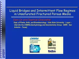
Liquid Bridges and Intermittent Flow Regimes in Unsaturated Fractured Porous Media. Dani Or and Teamrat Ghezzehei Dept. of Plants, Soils, and Biometeorology · Utah State University · Logan – Utah [for the CNWRA,Geohydrology and Geochemistry Group · SWRI · San Antonio – Texas].

E N D
Liquid Bridges and Intermittent Flow Regimes in Unsaturated Fractured Porous Media Dani Or and Teamrat Ghezzehei Dept. of Plants, Soils, and Biometeorology · Utah State University · Logan – Utah [for the CNWRA,Geohydrology and Geochemistry Group · SWRI · San Antonio – Texas]
Outline – Section 5 Unstable and intermittent flow • Primary flow regimes in unsaturated vertical fractures. • Onset of instability – fingering and intermittent flow. • Stability analysis for isolated liquid bridges. • Elongation and detachment of suspended liquid bridges. • Experimental results – effect of path priming. • Intermittency and a “chaotic-like” flux at a fracture base. • Inference of internal fracture geometry? (no avalanches) • Fingering, rivulet, and intermittent flow regimes in soils. • Governing forces for onset of flow instability - criteria. • Dimensional analysis – limits on applicability of Richards’ Eq.
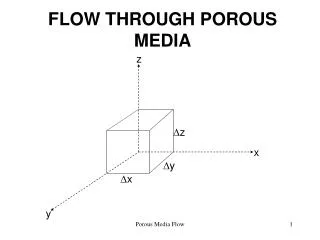
Introduction • Flow processes in unsaturated fractured porous media (FPM) are considerably different than flow in rock matrix due to enhanced gravitational forces in relatively large pore spaces. • Recent studies revealed coexistence of several flow regimes ranging from film flow on fracture surfaces (Tokunaga and Wan , 1997); Liquid bridges and liquid threads (Su et al., 1999); to intermittent rivulets (Kneafsey and Pruess, 1998). • The onset of any flow regime and transitions between various flow regimes are not fully understood. • The observed intermittent flow induced by formation and motion of liquid clusters is not amenable to representation by standard continuum theories.
Flow Processes in UnsaturatedNon-Horizontal Fractures Moving Bridges and Liquid Threads Film Flow on Rough Surfaces Liquid Bridges and Fingers Su et al., 1999 Rivulets Tokunaga and Wan, 1997 Or and Tuller, 1999 Nicholl et al, 1994
Forces on Liquid in Unsaturated Fractures Bond Number - gravitational relative to capillary forces Bo~0.05; 1000 larger than in soils (Su et al., 1999) Capillary Number – viscous relative to capillary forces Jeffery Number - gravitational relative to viscous forces Je=Bo/Ca Je~1000 with typical soils Je~1 (Su et al., 1999)
Force Balance for a Static Liquid Bridge Suspended in Non-Horizontal Fracture • Starting from a circular “seed bridge” fed by a constant flux, we seek to define: • Maximum bridge size. • Optimal configuration. • Capillary forces=Liquid weightFtop+Fbot+Fside=Weight • Bridge shape evolves via changes in-plane and out-of-plane liquid-vapor interfacial curvatures to match force exerted by liquid weight while minimizing overall energy.
Force Balance for a Static Liquid Bridge Suspended in Non-Horizontal Fracture • Given: b - aperture, V - volume, Ct, and - spanning angle, all other quantities (D, Cb, etc.) can be geometrically defined. With:
Optimal Configurations of Stationary Liquid Bridges • Optimal configurations of different liquid volumes held in a 0.8 mm fracture aperture with their solid-liquid perimeter length (representing interfacial energy per unit volume) as a function of bridge spanning angle ().
Optimal Configurations of Stationary Liquid Bridges in Non-Horizontal Fractures • Observed liquid bridges in an artificial fracture made of rough glass surfaces with aperture size of 0.66 mm [Su et al., 1999]. • Optimal configuration are calculated for estimated 200 mm3 liquid volume. Su et al., 1999 • Observed bridges are in motion at a rate of 0.5 cm/s. The calculated shape of stationary bridges will likely be less elongated under the influence of a drag force.
Finger Flow and Bridge Detachment in Non-Horizontal Fractures What happens when interfacial forces can no longer support liquid bridge weight?
Liquid Bridges and Intermittent Flow Regimes in Unsaturated Fractures Media Liquid Bridge Dripping
A Liquid bridge suspended from fracture discontinuity • A suspended bridge in a narrow asperity or a fault. • Geometry and curvature components of an elongating suspended liquid bridge.
Elongation and breakup of a suspended liquid bridge • Force components, their origin and direction in an elongating suspended liquid bridge (stresses due to viscous extension rate are not marked). • Liquid elements are labeled by a one-dimensional time-like element tracking Lagrangian coordinate (=0 the “oldest” water). • We seek to determine the largest bridge size that remains suspended, and subsequent dynamics of bridge elongation and eventual detachment (breakup).
Elongation of a suspended liquid bridge • Force components at a plane labeled t in an elongating liquid bridge. • Elongation stress is the so-called Trouton result for axial extension of a Newtonian fluid thread. • Assuming a wet or “primed” surface, we neglect solid-liquid interactions (i.e., viscous drag force). Longitudinal stress Elongation stress A = 4yb is the bridge cross-sectional area l=3h the Trouton (compression) viscosity R>1 surface roughness index v longitudinal extension velocity
Optimal Configurations and Sizes of Elongating Liquid Bridges • Suspended bridge volumes in vertical fractures as a function of aspect ratio () and three aperture sizes. (Symbols signify values of maximum bridge volume). • The results are used as boundary conditions for the dynamic elongation and detachment phases.
Liquid Bridge Width and Anchoring Area for Maximum Volume • The width of the largest bridge volume and the associated liquid bridge anchoring area as a function of fracture aperture size. • These results are used as boundary conditions for the dynamic elongation and detachment phases.
Liquid bridge detachment interval and detached volume • detachment interval (sec). • detached volume (mm3) as functions of volumetric flux (Q) in three different fracture apertures.
Experiments in an artificial fracture: Liquid bridge Formation and detachment A sequence of water bridge formation, elongation, and detachment in a 0.6 mm fracture model. Note the formation of a liquid thread feeding the “detaching” bridge volume similar to observations by Su et al. [1999].
Experimental Results Measurements (symbols) and model predictions (lines) of bridge detachment intervals as a function of input flux within two aperture sizes
Variations in Fracture Aperture & Output Flux Top view • Local variations in fracture aperture (asperities) induce different detachment intervals and volumes. • The resultant output flux often appears noisy and chaotic. • Interactions between input flux and fracture internal geometry affect output flux structure.
Can the structure of the flux be used to extract information on fracture internal geometry?
Complications due to avalanches in 2-D spaces • The mass within the region swept out by the sliding bridge wdy contributes to the increase in bridge mass ( is the liquid mass density in a fracture or windshield). • For a bridge with mass m and radius rm1/2 the mass increases as (y)2 and the width w(y) growth as y. • The problem here is that a small discharge event can trigger a disproportionally-large avalanche that could distort inferences on fracture internal structure. Cheng et al. 1989 (Phys. Rev. A 40:5922-5934)
Summary • Flow regimes in unsaturated fractures are a combination of film, finger and rivulet flows. • The gradual growth and subsequent breakup of a liquid bridge fed by film flow was modeled as a function of flux and aperture size. • Results show that flow from unsaturated fractures with complex internal geometry is intermittent with erratic and chaotic-like flux. • We explored the potential of using FFT analysis of flux at a control plane to identify features related to fracture internal structure. • The study highlights limitations of continuum approaches and suggest an alternative modeling approach based on discrete liquid elements.