Download

1 / 14
180 likes | 656 Vues
Workshop 4 Flow Through Porous Media. Introduction to CFX. Pardad Petrodanesh.Co Lecturer: Ehsan Saadati ehsan.saadati@gmail.com www.petrodanesh.ir. Introduction. This workshop demonstrates how to model porous media in CFX.

E N D
Workshop 4Flow Through Porous Media Introduction to CFX PardadPetrodanesh.Co Lecturer: Ehsan Saadati ehsan.saadati@gmail.com www.petrodanesh.ir
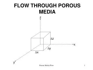
Introduction • This workshop demonstrates how to model porous media in CFX. • It models a catalytic converter. Nitrogen flows in through the inlet with a uniform velocity of 10 m/s, passes through a ceramic monolith substrate with square shaped channels, and then exits through the outlet. • The substrate is impermeable in the X and Y direction, which is modeled by specifying loss coefficients 2 orders of magnitude higher than in the Z direction. Ceramic Monolith Substrate
Starting CFX-Pre • Start Workbench and save the Project as cat_converter.wbpj • Drag CFX into the Project Schematic from the Component Systems toolbox and name the system Porous • Start CFX-Pre by double clicking Setup • When CFX-Pre opens, right-click Mesh and select Import Mesh > ICEM CFD. Select the file catconv.cfx5 • Keep the Mesh Units in m
Material Import • Right-click Materials and select Import Library Data • Select N2 Ideal Gas by expanding the Calorically Perfect Ideal Gases branch • Click OK
Fluid Domain Setup • Double-click Default Domain • For Fluid 1, set the Material to N2 Ideal Gas (note: use the icon) • Switch to the Fluid Models tab • Set Heat Transfer to Isothermal • Set Fluid Temperature to 450 [C] • Set Turbulence to k-epsilon • Click OK
Setting Up Boundary conditions • Insert a boundary condition named Inlet • Set Boundary Type to Inlet • Set Location to INLET • Switch to the Boundary Details tab • Set Mass and Momentum to a Normal Speed of 10 [m s^-1] • Click OK • Insert a Boundary Condition named Outlet • Set Boundary Type to Outlet • Set Location to OUTLET • Switch to the Boundary Details tab • Enter a Relative Pressure of 0 [Pa] • Click OK
Setting Up Porous Domain • Right-click on Flow Analysis 1 and insert a Domain named Substrate • Set the Location to SUBSTRATE • Set the Domain Type to Porous Domain • Switch to the Porosity Settings tab • Set Volume Porosity to 0.5 • Set the Loss Model option to Directional Loss • For the Streamwise Direction, enter components of 0,0,1 • Set Streamwise Loss to Linear and Quadratic Resistance Coefficients • Turn on Quadratic Resistance Coefficient and enter a value of 440 [kg m^-4] • Set the Streamwise Coefficient Multiplier to 100 and click OK
Domain Interface CFX automatically creates a Fluid-Porous interface between the Default Domain and Substrate. You can double-click Default Fluid-Porous Interface to view the setup, or highlight the Default Fluid Porous Interface Side 1 and Default Fluid Porous Interface Side 2 boundaries in the individual domains to see that that regions are correct.
Output Control • Edit Output Control from the Outline tree • Switch to the Monitor tab and turn on Monitor Options • Click to create a new monitor object, and call it Mass Flow at Outlet • Set the Option to Expression • Set the Expression Value to massFlow()@Outlet • Insert a new object in the same way called Pressure Drop, using the Expression: • Click OK Right-click massFlowAve(Total Pressure)@REGION:INLETSUBSTRATEINTERFACE_1 -massFlowAve(Total Pressure)@REGION:OUTLETSUBSTRATEINTERFACE_1
Starting Solver • Close CFX-Pre and save the project • Double-click Solution to start the Solver Manager • When the Solver Manager opens click Start Run At the end of the run, click the User Points tab and click the green line where it flattens out. It reports a pressure drop value of approx 285 Pa across the substrate
Post-processing • When the solver finishes, close the Solver Manager • Double-click on Results in the Project page to start CFD-Post • Once CFD-Post is open, select Location > Plane from the toolbar • Set Method to ZX Plane • Set Y to 0 [m] • Click Apply • Turn off Visibility for Plane 1 by disabling the check-box next to its entry in the Outline tree • Select Insert > Vector • Select Locations to Plane 1 • Click Apply
Post-processing • Hide the Vector plot created in the last step • Select Insert > Contour • Set Locations to Plane 1 • Set Variable to Pressure • Click Apply
Post-processing • Select Location > Line from the toolbar • Set Point 1 to 0,0,-0.07 • Set Point 2 to 0,0,0.07 • Click Apply • Select Insert > Chart • On the General tab enter Pressure in Porous Domain as the Title • On the Data Series tab, click to create Series 1 • Set Location to Line 1 • On the X Axis tab, set Variable to Z • On the Y Axis tab, set Variable to Pressure • Click Apply
Post-processing • Switch to the Expressions tab • Right-click and select New • Enter the Name as deltaP and enter the Definition as:massFlowAve(Total Pressure)@Inlet - massFlowAve(Total Pressure)@Outlet • Click Apply to evaluate the expression The value should come out to be approximately 300 Pa. Since we know from the solver monitor value that approx. 285 Pa or Total Pressure is lost across the substrate, we can determine that 15 Pa is lost through the rest of the device.