Download
1 / 11
120 likes | 241 Vues
3D Fluid Flow Through a Chamber Separated by a Porous Membrane a Finite Element Analysis (FEA) Numerical Model. Craig E. Nelson - Consultant Engineer. The Model Assumptions. Inlet fluid flows into an inlet chamber through a small inlet port “slot” in a lower “basement” chamber

E N D
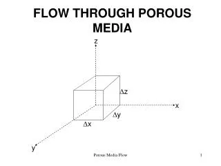
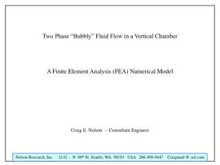
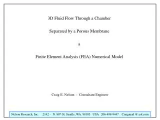
3D Fluid Flow Through a Chamber Separated by a Porous Membrane a Finite Element Analysis (FEA) Numerical Model Craig E. Nelson - Consultant Engineer
The Model Assumptions • Inlet fluid flows into an inlet chamber through a small inlet port “slot” in a lower “basement” chamber • Outlet fluid flows out of an upper “attic” chamber through a small outlet port “slot” • All fluid flows through the porous silicon membrane in an “out of the plane” Z axis direction • Fluid pressures and flow rates are “nominal” • The Z Axis Scaling is Expanded by a Factor of 10 for Clarity of Presentation
Computed Lines of Flow Outlet Port Inlet Port Outlet “Attic” Chamber Porous Silicon Membrane Inlet “Basement” Chamber Geometry for the Numerical Flow Model (Vertical Z Axis is Amplified by a Factor of 10 From the True Geometry)
Left Cell Window Border Outlet Port on Lower Right Side of Upper “Attic” Channel Porous Membrane Right Cell Window Border Inlet Port on Upper Left Hand Corner of the Lower “Basement” Channel Pressure Distribution on Left and Right Cell Window Borders (1000 Pa at Inlet – 0 Pa at Outlet)
Left Cell Window Border Outlet Port on Lower Right Side of Upper “Attic” Channel Porous Membrane Right Cell Window Border Inlet Port on Upper Left Hand Corner of the Lower “Basement” Channel X Direction Velocity Distribution on Left and Right Cell Window Borders
X = 0 Center Plane Y = 0 Center Plane Porous Membrane X direction Velocity Y direction Velocity Velocity Distributions on X=0 and Y=0 Cell Window Center Planes
Y = Inlet Port Center Plane Y = Inlet Port Center Plane Porous Membrane X – Z Vector Velocity X – Y – Z Velocity Magnitude Velocity Distributions on Inlet and Outlet Port Center Planes
Y = Outlet Port Center Plane Y = Outlet Port Center Plane Porous Membrane X – Z Vector Velocity X – Y – Z Velocity Magnitude Velocity Distributions on Outlet Port Center Plane
Z = “Basement” Inlet Port Center Plane Z = “Basement” Inlet Port Center Plane Inlet Port X – Y Vector Velocity X – Y – Z Log10 Velocity Magnitude Velocity Distribution on Z Axes “Basement” Inlet Port Center Plane
Z = “Attic” Outlet Port Center Plane Z = “Attic” Outlet Port Center Plane Outlet Port X – Y Vector Velocity X – Y – Z Log10 Velocity Magnitude Velocity Distribution on Z Axes “Attic” Outlet Port Center Plane
Summary • The inlet chamber pressure is almost constant across the membrane surface • In plane velocity falls rapidly to nearly zero a short distance away from the fluid inlet ports • Velocity in the inlet and outlet ports will be several orders of magnitude larger than in most parts of the fluid “Attic” and “Basement” Chambers • High inlet fluid velocity may provide a measurable pressure drop in the inlet port feed “pipe”. • High outlet fluid velocity and a small outlet orifice and related take-away “pipe” will probably interfere with bubble removal from the the “Attic” outlet chamber.