Download
1 / 48
480 likes | 683 Vues
+. CV includes the fluid stream only, no solid part. Lecture 6.2.1: C-Energy for A Steady, Incompressible, Fluid Stream: Conservation of Mechanical Energy and Mechanical Energy Loss (ME Loss).

E N D
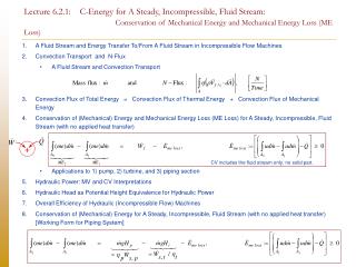
+ CV includes the fluid stream only, no solid part. Lecture 6.2.1: C-Energy for A Steady, Incompressible, Fluid Stream: Conservation of Mechanical Energy and Mechanical Energy Loss (ME Loss) • A Fluid Stream and Energy Transfer To/From A Fluid Stream in Incompressible Flow Machines • Convection Transport and N-Flux • A Fluid Stream and Convection Transport • Convection Flux of Total Energy = Convection Flux of Thermal Energy + Convection Flux of Mechanical Energy • Conservation of (Mechanical) Energy and Mechanical Energy Loss (ME Loss) for A Steady, Incompressible, Fluid Stream (with no applied heat transfer) • Applications to 1) pump, 2) turbine, and 3) piping section • Hydraulic Power: MV and CV Interpretations • Hydraulic Head as Potential Height Equivalence for Hydraulic Power • Overall Efficiency of Hydraulic (Incompressible Flow) Machines • Conservation of (Mechanical) Energy for A Steady, Incompressible, Fluid Stream (with no applied heat transfer) [Working Form for Piping System]
N-Flux at 1 N-Flux at 2 1 2 Very Brief Summary of Important Points and Equations [1] • A steady, incompressible fluid stream: • the energy of a fluid stream, N = Energy, • the convection of energy (through a cross section A, from one place to another): • of a fluid stream, and • the addition of energy to (pump), and the extraction of energy from (turbine), a fluid stream. • The decomposition of energy into two forms: • Thermal Energy (TE, U) + Mechanical Energy (ME) • The convection of energy of a fluid stream at any one cross section can be decomposed into • 1) the convection of thermal energy (u) + 2) the convection of mechanical energy (me):
+ CV includes the fluid stream only, no solid part. Work of all surface forces (excluding the flow work, pv, at inlet and exit), e.g., work of shear at CS, works of pressure and shear at pump and/or turbine rotating impeller surface. Very Brief Summary of Important Points and Equations [2] 4. C-(ME)-Energy and ME Loss for A Steady, Incompressible, Fluid Stream (with no applied heat transfer) • Physical Interpretation: • The above C-Energy equation can be viewed as a • conservation of mechanical energy (ME) of a fluid stream. • The rise in mechanical energy/power of the fluid stream as it flows from 1 to 2 • = ME added to the fluid stream as work of all surface forces (excluding flow work) • - ME Loss in CV (Irreversible conversion of ME to TE)
Potential head/height equivalence (at the same mass flowrate ), H pump Recall the coincident MV(t) and CV(t) = Hydraulic Power [MV Viewpoint] := the time rate of change of mechanical energy of the fluid stream[ENERGY STORED] as it flows through CV [from CV inlet 1 to CV exit 2]. [CV Viewpoint] := Increase/Decrease in ME Flux of the fluid stream from CV inlet 1 to CV exit 2 Hydraulic Head where Very Brief Summary of Important Points and Equations [3] • Hydraulic Power and Hydraulic Head
Very Brief Summary of Important Points and Equations [4] 6. C-(ME)-Energy and ME Loss for A Steady, Incompressible, Fluid Stream (with no applied heat transfer) • Physical Interpretation: • The above C-Energy equation can be viewed as a • conservation of mechanical energy (ME) of a fluid stream. • The rise in mechanical energy/power of the fluid stream as it flows from 1 to 2 • = ME added to the fluid stream at pump • - ME extracted from the fluid stream at turbine • - ME Loss in CV (Irreversible conversion of ME to TE)
No mass flow through side wall Mass flux: Mass flux: 1 2 1 Turbine 2 Pump a b c d Mass flux: Mass flux: A Fluid Stream A stream tube as a fluid stream (stream surface as an imaginary side wall) A section of a piping system as a fluid stream A fluid stream here refers to • A stream of flowing fluid (we may choose a CV that excludes any solid part). Its side wall can be • real solid boundary, e.g., • a stream of fluid flowing between two sections (1 and 2) of a pipe, or • imaginary wall, e.g., • a stream of fluid flowing in a stream tube.
Example 1: CV includes the fluid stream, the solid impeller, and a section of the solid shaft. It cuts through the cross section of a solid shaft. Shaft Work Energy transfer as work at the rotating shaft cross section 1 CV1 / MV1 Turbine Pump 2 a 1(pump) b 2(pump) c 1(turbine) d 2(turbine) 2 1 Example 2: CV includes the fluid stream only, no solid part. Impeller Work Energy transfer as work at the rotating impeller surface 1 CV2 / MV2 Turbine Pump 2 2 1 a 1(pump) b 2(pump) c 1(turbine) d 2(turbine) Example: Energy Transfer To/From A Fluid Stream Choices of Control Volumes for A Fluid Stream, 1) Forces and FBD, and 2) Energy Transfer as Work of Forces
CV1 / MV1 CV1 / MV1 ME2 ME1 ME2 ME1 2 1 2 1 CV2 / MV2 CV2 / MV2 ME2 > ME1 ME2 < ME1 • Pump • Add (mechanical) energy to the fluid stream • Turbine • Extract (mechanical) energy from the fluid stream. Pump: A Cascade of Energy Transfers as Work Through 1) Rotating Shaft and 2) Rotating Impeller, and Finally To 3) the Fluid Stream Turbine: The Direction is Reversed Incompressible flow machines
Pressurep Coincident MV(t) and CV(t) Sheart CV(t) MV(t) 3. Stationary imaginary surface Solid part 1. Moving solid surface 2. Stationary solid surface Recall Relation Between 1) Forces and FBD and 2) Energy Transfer as Work of (All) Forces FBD and Energy Transfer as Work of All Forces • C-Energy: In the application of C-Energy, we must find energy transfer as work of all forces ( )thatact on our coincident MV/CV. • FBD: We should then recognize/draw a FBD for all the forces that act on our coincident MV/CV.
Inlet and Exit (stationary imaginary surface) • Pressure • Work of pressure is included as flow work pv. • Shear • If velocity is to the CS – hence to shear, no work of shear. • Stationary solid surface (no-slip) • Pressure and shear • No work from both pressure and shear pv • Moving solid surface (no-slip) • Pressure and shear • There are works from both pressure and shear Note: This shear work is often neglected in comparison to the flow work. 1 Turbine Pump 2 a 1(pump) b 2(pump) c 1(turbine) d 2(turbine) Example 1: FBD and Work Piping System:CV includes the fluid stream only, no solid part.
Stationary imaginary surface (streamlines) • Pressure • Pressure is velocity, no work of pressure • Shear • There is work of shear. • Inlet and Exit (stationary imaginary surface) • Pressure • Work of pressure is included as flow work pv. • Shear • If velocity is to the CS – hence to shear, no work of shear. pv CS is streamline Note: This shear work is often neglected in comparison to the flow work. 1 2 Streamlines Example 2: FBD and Work Stream Tube:CV includes the fluid stream only, no solid part.
A 1 2 Mass flux: N flux: Convection (Transport) and N-Flux • The mass flux/flowrate carries with it (its own property) the flux/flowrate of Nthrough a cross section A. • This results in a convection transport of physical quantities(mass, momentum, energy, etc.) from one place to another.
1 2 Mass flux: Mass flux: N-flux: N-flux: 1 Turbine 2 Pump a b c d • In this topic, we shall focus on • the energy of the fluid stream, N = Energy, • the convection of energy (from one place to another) of the fluid stream, and • the addition of energy to (pump), and the extraction of energy from (turbine), the fluid stream.
Convection Flux of Total Energy = Convection Flux of Thermal Energy + Convection Flux of Mechanical Energy
Mechanical Energy Flux through a cross section A Pump 1 2 • For an incompressible flow machines (hence, for turbine, it is often called hydraulic turbine): • Pumpadds mechanical energy (me) to the fluid stream to increase the me of the stream • via energy transfer as work through shaft and impeller • Turbine extracts mechanical energy (me) from the fluid stream to convert it to useful shaft work • via energy transfer as work through impeller and finally shaft • It is then convenient to decompose • Convection flux of total energy (E) • = Convection flux of thermal energy (TE) + Convection flux of mechanical energy (ME) Convection Flux of Energy = Convection Flux of Thermal Energy (TE) + Convection Flux of Mechanical Energy (ME)
Conservation of (Mechanical) Energy and Mechanical Energy Loss (ME Loss) for A Steady, Incompressible, Fluid Stream (with no applied heat transfer)
+ C-Energy for A MV C-Energy (Working Forms) for A CV e-pv - form u-me - form h - form ho - form = stagnation enthalpy Recall: C-Energy
+ • Assumptions: • Incompressible flow (r is steady and uniform) • All flow properties are steady (or steady-in-mean) • No energy transfer as heat (no applied heat transfer ) except that is associated with ME Loss. 1 2 1 Turbine 2 Pump CV: CV includes the fluid stream only, no solid part. a b c d C-Energy Net Convection Efflux Term Net (ME) Energy Transfer as Work Work of all surface forces (excluding the flow work, pv, at inlet and exit), e.g., work of shear at CS, works of pressure and shear at pump and/or turbine rotating impeller surface. Net Energy Transfer as Heat No energy transfer as heat (no applied heat transfer ) except that is associated with ME Loss. Conservation of (Mechanical) Energyfor A Steady, Incompressible, Fluid Stream (with no applied heat transfer) Unsteady Term
+ 1 2 1 Turbine 2 Pump a b c d ME2 ME1 TE1 TE2 Work of all surface forces (excluding the flow work, pv, at inlet and exit), e.g., work of shear at CS, works of pressure and shear at pump and/or turbine rotating impeller surface. C-Energy Separate thermal energy from mechanical energy and group corresponding terms together:
+ 1 2 1 Turbine 2 Pump a b c d The rise in mechanical energy of the fluid stream – from 1 to 2 – as measured by the difference in ME (me flux) is equal to + (mechanical) energy added to the fluid stream as work (of surface forces) - the thermal energy term ME2 ME1 TE2 TE1
1 2 1 Turbine 2 Pump a b c d It can be proven from the second law of thermodynamics (see appendix) that, this thermal energy term – which we shall denote it by represents the time rate of irreversible conversion of mechanical energy to thermal energy according to the second law of themodynamics, or mechanical energy loss (ME Loss). Mechanical Energy Loss: Irreversible Conversion of Mechanical Energy to Thermal Energy According to the Second Law of Thermodynamics
+ • Assumptions: • Incompressible flow (r is steady and uniform) • All flow properties are steady (or steady-in-mean) • No energy transfer as heat (no applied heat transfer ) except that is associated with ME Loss. 1 2 1 Turbine 2 Pump a b c d Work of all surface forces (excluding the flow work, pv, at inlet and exit), ME1 ME2 C-Energy for A Steady, Incompressible Fluid Stream(with no applied heat transfer) CV includes the fluid stream only, no solid part.
CV1 / MV1 ME2 ME1 2 1 CV2 / MV2 ME2 > ME1 = Mechanical energy that the fluid stream actually receives from inlet 1 to exit 2. ME loss at bearings, etc. ME loss due to friction in the fluid stream itself in the pump (between 1 and 2). • Recall the shear stress/Newton’s viscosity law in Chapter 2. • Rubbing your hands together and they get warmer; friction converts mechanical energy (kinetic energy) to thermal energy. 1] Pump: Application of C-Energy for A Steady, Incompressible Fluid Stream Here, we use CV2/MV2 • Impeller transfers (mechanical) energy as work at its surface to the fluid stream (+100 W). • ME loss – ME being irreversibly converted to TE - in the stream as it flows from 1 to 2 (+20 W). [The loss occurs throughout the whole volume in CV.] • The stream emerges at exit 2 with only (+80 W) more mechanical power than at inlet 1.
CV1 / MV1 ME2 ME1 2 1 CV2 / MV2 ME2 < ME1 = Mechanical energy that the fluid stream actually gives up from inlet 1 to exit 2. ME loss at bearings, etc. ME loss due to friction in the fluid stream itself in the turbine (between 1 and 2). • Recall the shear stress/Newton’s viscosity law in Chapter 2. • Rubbing your hands together and they get warmer; friction converts mechanical energy (kinetic energy) to thermal energy. 2] Turbine: Application of C-Energy for A Steady, Incompressible Fluid Stream Here, we use CV2/MV2 • The fluid stream gives up its mechanical power as it flows from 1 to 2 (-100 W). • ME loss – ME being irreversibly converted to TE - in the stream as it flows from 1 to 2 by (+20 W) [The loss occurs throughout the whole volume in CV.] • The impeller actually receives the transfer of energy as work at its surface from the fluid stream only (- 80 W).
ME1 ME2 ME2 < ME1 3] Pipe Section:Application of C-Energy for A Steady, Incompressible Fluid Stream • Due to ME loss – ME being irreversibly converted to TE - in the stream as the fluid stream flows from 1 to 2, the stream emerges at 2 with (+20 W) less mechanical power than when it enters at 1.
Hydraulic Power: MV and CV Interpretations
= ME flux through cross section A ME1 ME2 Hydraulic Power [CV Viewpoint] 1 2 Hydraulic Power [MV Viewpoint] Hydraulic Power: = the time rate of change of mechanical energy of the fluid stream[ENERGY STORED] as it flows through CV [from CV inlet 1 to CV exit 2]. Hydraulic Power: MV and CV Interpretations • Since we are interested in the change in mechanical energyof the fluid stream as it flows through CV, from CV inlet 1 to CV exit 2, we define Recall the coincident MV(t) and CV(t) The two views are equivalent, see next slide.
coincident MV RTT: ME1 ME2 1 2 MV View CV View MV and CV Aspect of Hydraulic Power: Another Application of RTT The coincident MV has the time rate of change of its mechanical energy = the net convection efflux of me = ME2 – ME1 =: Hydraulic Power
Part of the original MV flows out to Region III coincident MV(t) and CV(t) at time t CV(t) at time t+dt III I II New – but not yet of interest - MV flows into Region I MV (t+dt) Original MV at some later time t+dt The original MV that instantaneously coincides with the CV has the instantaneous time rate of increase of mechanical energy = Recall The Three Regions I – II – III in the derivation of RTT
= the time rate of change of mechanical energy of the fluid stream [ENERGY STORED] as it flows through CV [from CV inlet 1 to CV exit 2]. • Hydraulic Power • is the property of the fluid stream, not that of the solid shaft. • must be evaluated from the properties of the fluid stream(i.e., pressure of fluid p, specific volume of fluid v, velocity of fluid V, etc.) - not that of the solid shaft. ME1 ME2 1 2 • NOTE • The term hydraulic “power” can be little misleading. • It may cause confusion that this is the time rate of work of force (ENERGY TRANSFER). It is not. • It is the time rate of change of mechanical energy of the fluid stream (ENERGY STORED). Some Aspects of Hydraulic Power
Impeller Power Shaft Power Hydraulic Power 1 1 2 2 1 2 Properties of fluid stream, not those of solid shaft, e.g., pressure p of fluid, velocity V of fluid, etc. Impeller work [Mechanical] Energy transfer as work (between the moving solid impeller and the fluid stream) at the moving solid impeller surface. (Solid-Fluid Interaction] Shaft Work [Mechanical] Energy transfer as work (between one part of the solid shaft to another part of the solid shaft) at the solid cross section of a shaft. Hydraulic Power The actual amount of mechanical energy me that the fluid stream receives/gives up from inlet 1 to exit 2. Hydraulic Power VS Impeller Power VS Mechanical Power at Shaft
Hydraulic Head as Potential Height Equivalence for Hydraulic Power
Potential head/height equivalence (at the same mass flowrate ), H pump = For ease of grasping the physical sense of the magnitude of the hydraulic power, we equate the hydraulic power to the amount of power that is required to lift the fluid at the same mass flowrate to the heightH (hydraulic head), i.e., Hydraulic Head where Hydraulic Power and Hydraulic Head H as the Potential Power Equivalence
Hydraulic HeadH at m m In order to determine the hydraulic power, the hydraulic headHmust be stated together with the mass flowrate ( ) since, according to the definitions Stating only the headHis not enough. Hydraulic Power and Hydraulic Head H
Overall Efficiency of Hydraulic (Incompressible Flow) Machines Pump and (Hydraulic) Turbine Note: Not Gas or Steam Turbine where the flow inside is compressible.
Mechanical power that the fluid stream receives from inlet 1 to exit 2 PUMP = Hydraulic Power Overall Pump Efficiency Mechanical power input at shaft Turbine Mechanical power output at shaft Overall Turbine Efficiency Mechanical power that the fluid stream gives up from inlet 1 to exit 2 = Hydraulic Power Overall Efficiency of Pump and (Hydraulic) Turbine
Hydraulic Power Impeller Power Shaft Power PUMP Overall Pump Efficiency 1 1 1 1 2 2 2 2 1 1 2 2 ME loss due to friction in the fluid stream itself in the pump (between 1 and 2). ME loss due to friction in the fluid stream itself in the pump (between 1 and 2). ME loss at bearings, etc. ME loss at bearings, etc. For simplicity in notation, later on we shall drop the ‘s’ for ‘shaft.’ Turbine Overall Turbine Efficiency
Conservation of (Mechanical) Energy and Mechanical Energy Loss (ME Loss) for A Steady, Incompressible, Fluid Stream (with no applied heat transfer) [Working Form for Piping System]
Her, we consider many CV’s and sum their equations together. CV’s include fluid stream only, no solid part. 1 LHS = ME change from inlet to exit CV: 1-a (pipe) + Turbine Pump 2 a 1(pump) b 2(pump) c 1(turbine) d 2(turbine) CV: a-b (pump) + CV: b-c (pipe) + CV: c-d (turbine) + CV: d-2 (pipe) CV: 1 2
1 2 • Assumptions: • Incompressible flow (r is steady and uniform) • All flow properties are steady (or steady-in-mean) • No energy transfer as heat (no applied heat transfer ) except that is associated with ME Loss. 1 Turbine Pump 2 a 1(pump) b 2(pump) c 1(turbine) d 2(turbine) Physical Interpretation: The above C-Energy equation can be viewed as a conservation of mechanical energy (ME) of a fluid stream. The rise in mechanical energy/power of the fluid stream as it flows from 1 to 2 = ME added to the fluid stream at pump - ME extracted from the fluid stream at turbine - ME Loss in CV (Irreversible conversion of ME to TE) Conservation of (Mechanical) Energy for A Steady, Incompressible, Fluid Stream(with no applied heat transfer)
1 2 1 Turbine Pump 2 a 1(pump) b 2(pump) c 1(turbine) d 2(turbine) • Physical Interpretation: • The above C-Energy equation can be viewed as a • conservation of mechanical energy (ME) of a fluid stream. • ME at 2 = ME at 1 (starting ME) + Increase in ME at pump • - Decrease in ME at turbine • - ME Loss in CV (Irreversible conversion of ME to TE, piping sections) “Walking” (from 1 to 2) Interpretation
Chapter 10: Turbomachine We will learn how to find the hydraulic power and hydraulic head for idealized machines in terms of the machine’s geometrical and kinematical parameters. Chapter 8: Viscous Internal Flow We will learn how to correlate ME Loss in piping components in terms of mechanical quantities (not thermal quantities). Chapter 6: Bernoulli’s Equation For a steady incompressible flow in a stream tube, in the absence of energy transfer as work and in the absence of friction (ME Loss), mechanical energy of the fluid stream is conserved. For an infinitesimal stream tube, i.e., a streamline, this becomes the conservation of mechanical energy along the streamline. What’s coming up?
1 2 1 • Assumptions: • Incompressible flow (r is steady and uniform) • All flow properties are steady (or steady-in-mean) • No energy transfer as heat (no applied heat transfer ) • except that is associated with ME Loss. • No energy transfer as work of surface forces, • except the flow work pv. Turbine 2 Pump a b c d • No energy transfer as heat or work except • heat transfer that is associated with ME Loss, and • the flow work pv. ME Loss is simply the difference between ME at 1 and 2. Special Case 1: No energy transfer as heat or work except heat transfer that is associated with ME Loss.
1 2 1 • Assumptions: • Incompressible flow (r is steady and uniform) • All flow properties are steady (or steady-in-mean) • No energy transfer as heat. • No energy transfer as work (except the flow work pv). • No ME Loss, . [Essentially, we assume no friction/viscous force, i.e., inviscid flow.] Turbine 2 Pump a b c d No energy transfer as heat or work, except the flow work pv. In chapter 6: Incompressible, Inviscid flow, we will derive this Bernoulli’s equation from another principle, the C-Mom Equation. • In the absence of • 1) energy transfer as heat or work (except the flow work pv), and • 2) ME Loss, • the mechanical energy of a steady, incompressible fluid stream is conserved. • This leads to the Bernoulli’s equation as the Conservation of Mechanical Energy Equation for such a fluid stream Special Case 2: No energy transfer as heat or work. NO ME Loss,
If the flow is incompressible, ME cannot be converted to TE via this mode, and vice versa. 1. ME transfer as work of force cannot be converted to TE. ME transfer as work of force results in increase in ME of the MV only. 2. TE transfer as heat cannot be converted to ME. TE transfer as heat results in increase in TE of the MV only. 1. Compressibility (Compression/Expansion work) Reversible process, ME and TE can be converted back and forth ME TE If the flow is inviscid, ME cannot be converted to TE via this mode. 2. Friction / Viscous Dissipation Irreversible process, convert ME to TE only ME TE NOTE: Conversion Between ME and TE Two mechanisms that can cause transformation between ME and TE
As a result, • for a 1. steady, • 2. incompressible (No reversible ME TE conversion via compressibility), • 3. inviscid flow (No irreversible ME TE conversion via viscous dissipation), • [MV view] the mechanical energy of the coincident MV in a fluid stream, or • [CV view] the mechanical energy flux through any cross section of the coincident CV in the fluid stream, • is conserved. • This is true even though there is energy transfer as heat so long as the flow remains incompressible, since the incompressibility condition suppresses TE ME via mechanism 1. There can be heat transfer, but it only results in the increase in TE (u) in incompressible flow. • Certainly, in order for the ME to be conserved there can be no (mechanical) energy transfer as work since that will affect the ME of the fluid stream directly, • Finally, in order for • [MV view] the mechanical energy of the coincident MV in a fluid stream, or • [CV view] the mechanical energy flux through any cross section of the coincident CV in the fluid stream, • to be conserved (in case of CV, conserved = ME flux through any cross sections remain the same), the assumptions in Special Case 2 can be replaced by the above 3 assumptions • + 4. no energy transfer as work. • [ 1) Drop the no energy transfer as heat assumption, and 2) replace no ME Loss by inviscid/no friction. ] Special Case 2: C-ME Energy in Relation to the The Bernoulli’s Equation NOTE: If the fluid is a compressible fluid such as air, energy transfer as heat generally couples with the change in density, hence not an incompressible flow and the above result does not apply.
+ 1 2 A simple way to think about this: But, if ds and dq/Tare to have some definite values, their difference must equal something, [ let that something be called dPs : ] and that something has to be non-negative, . MV, CV In order to consider the ME Loss, we consider the coincident MV: Second law of thermodynamics: Rewrite it in a more convenient form: (1) where dPs is the production in entropy and is never negative: . Gibb’s equation for a simple compressible substance: (2) (1) = (2): For incompressible flow,dv = 0. Thus, With the above assumptions, this equation basically states that the sum of the net increase in TE of an incompressible system and the net (TE) energy transfer out as heat (-dq) is never negative. APPENDIX (Related Proof for)ME Loss = Irreversible Conversion of ME to TE According to The Second Law of Thermodynamics Recall the RTT and the relation between the coincident MV and CV.